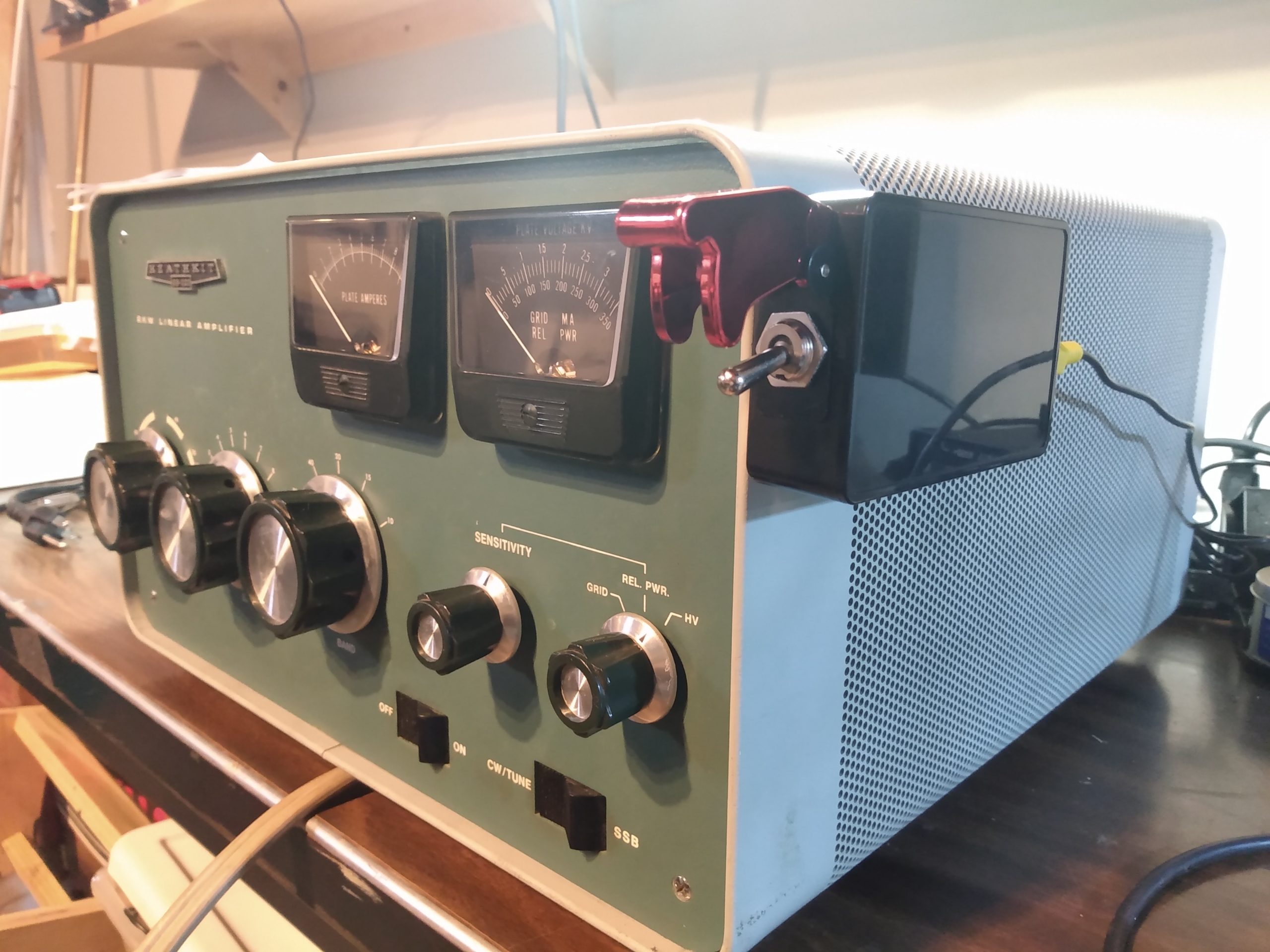
This is my Heathkit SB-220 amplifier. There are many like it, but this one is mine.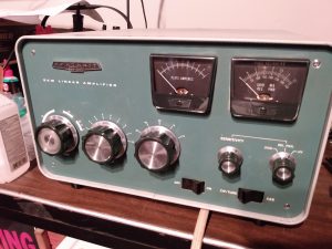
I wasn’t specifically looking for a new amplifier when I found this SB-220 on the QTH.com classifieds, but the price was worth the constituent parts of the amp on their own, never mind the two 3-500ZG tubes, so I knew it would be a worthwhile project no matter what shape it was in. After spending so much time attempting to repair my AL-80A I had developed an affinity for older tube gear, and I was intrigued and allured by the prospect of owning a tube amplifier that would get me over 1KW of RF and close to legal limit power.
I asked a few questions, and got a few answers. The seller had purchased it from a SK estate (couldn’t remember who) and didn’t know if anything had been done to it, but it did power on. After working out details with the seller and giving him a chance to test the amp, it was time to pick it up. With a promise to buy her dinner, the wife and I left town around 3PM on a Friday afternoon and started the 2 hour drive to Wilkes-Barre PA to pick it up.
Dinner was at Breaker Brewing Company in Wilkes-Barre, we got loaded nachos and paninis. Would recommend.
Upon return to the QTH, the SB-220 went straight to the bench. I didn’t even turn it on, because I wasn’t interested in how it operated now – I would be changing things. I wanted to know what I was dealing with first.
A note on disassembly of the SB220: It is time consuming. The entire chassis lives within a single piece outer shell, and removing the chassis requires orienting the amplifier in several different positions. This amplifier is HEAVY. Once the chassis is removed from this outer shell, the high voltage area of the amp is still sealed behind a panel with at least 12 screws. On my amplifier these screws had no less than 3 different heads. This also foreshadows the re-assembly of the SB-220…
“It appears to be mostly original”
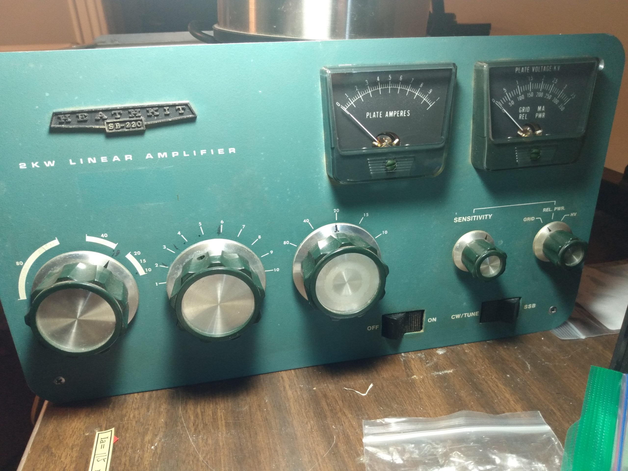
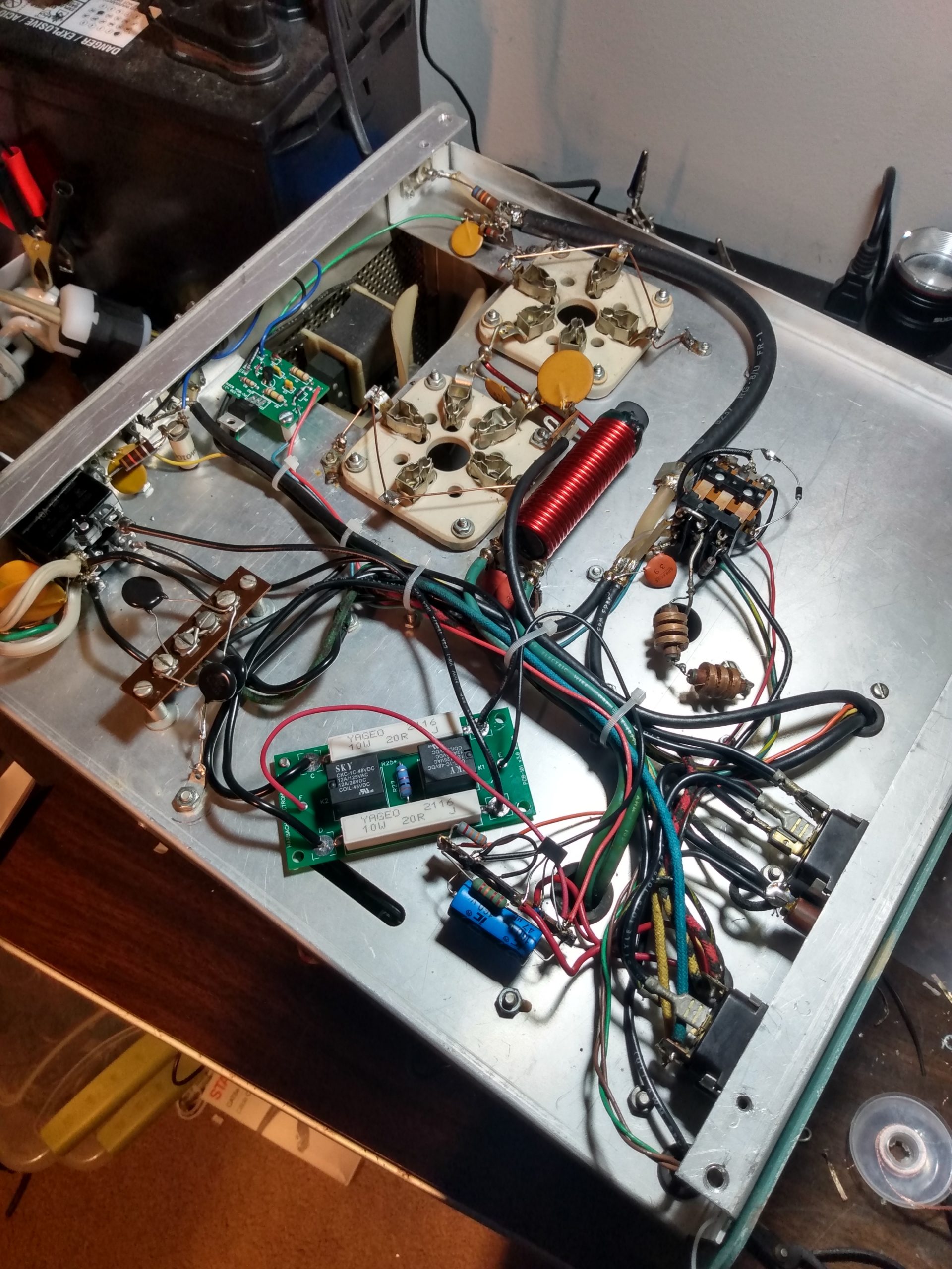
The following images are the SB-220 out of its shell, before I made any changes. The meters and knobs appeared to be original. The knobs showed some wear, but this builds character so they won’t be replaced.

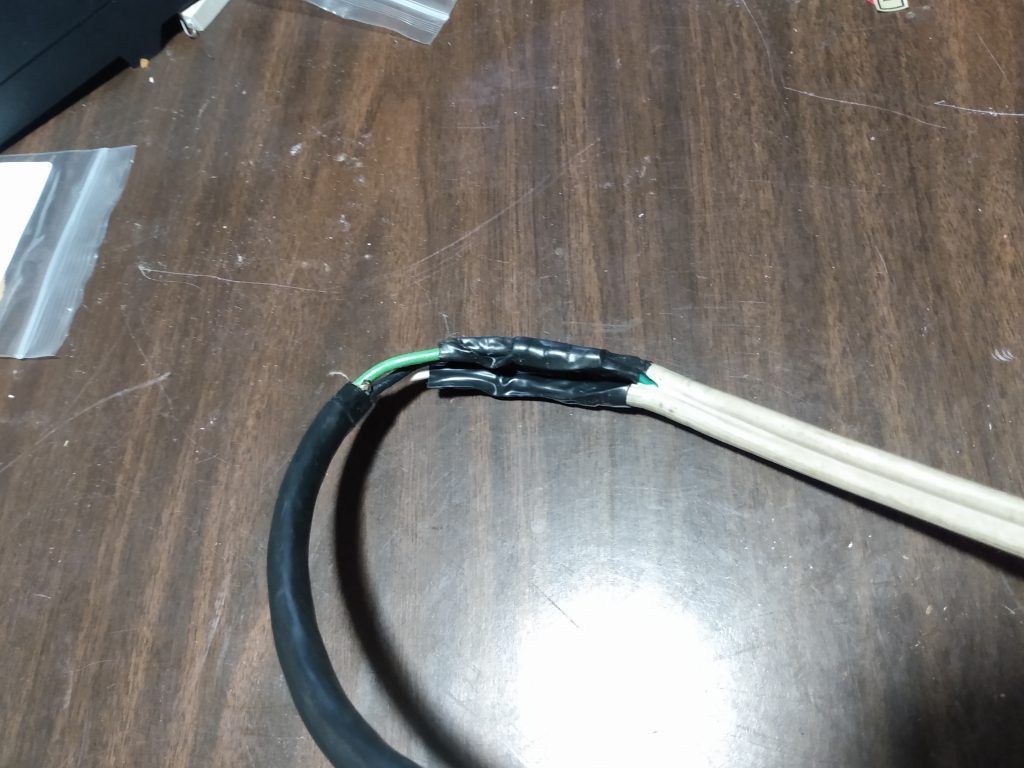
The stock power cable had been extended, presumably because the OM who had last used it needed a few more feet to get to his 240v outlet. It was ugly, but spliced correctly and appeared to be fully functional. This extension would be removed and a new 240v 6-15R plug put in its place. I did not need the extra wire length because my 240v outlet is directly next to my radio rack.
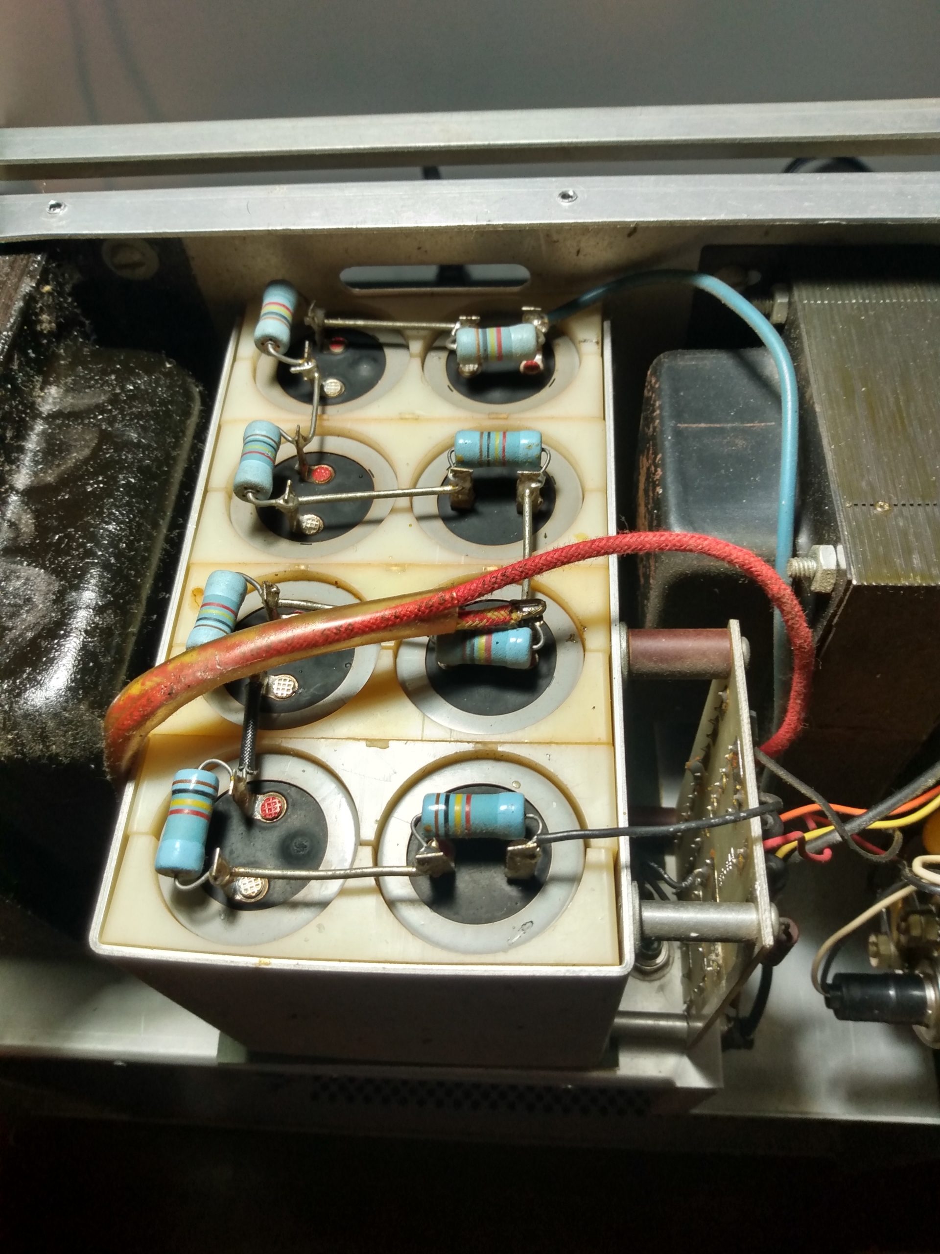
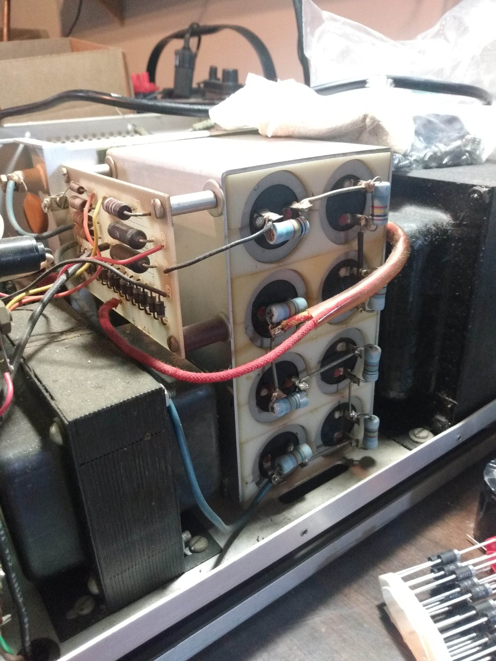
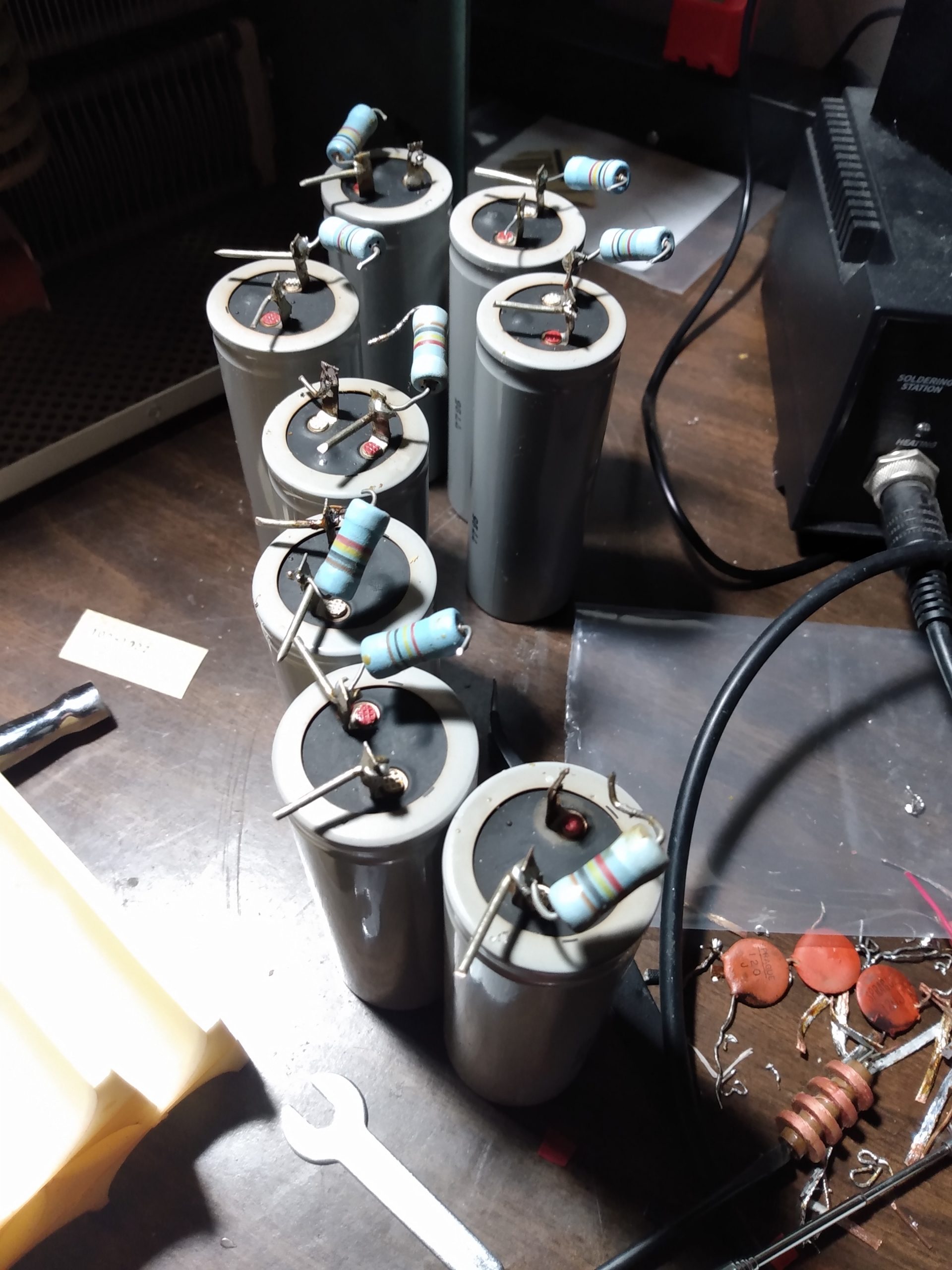
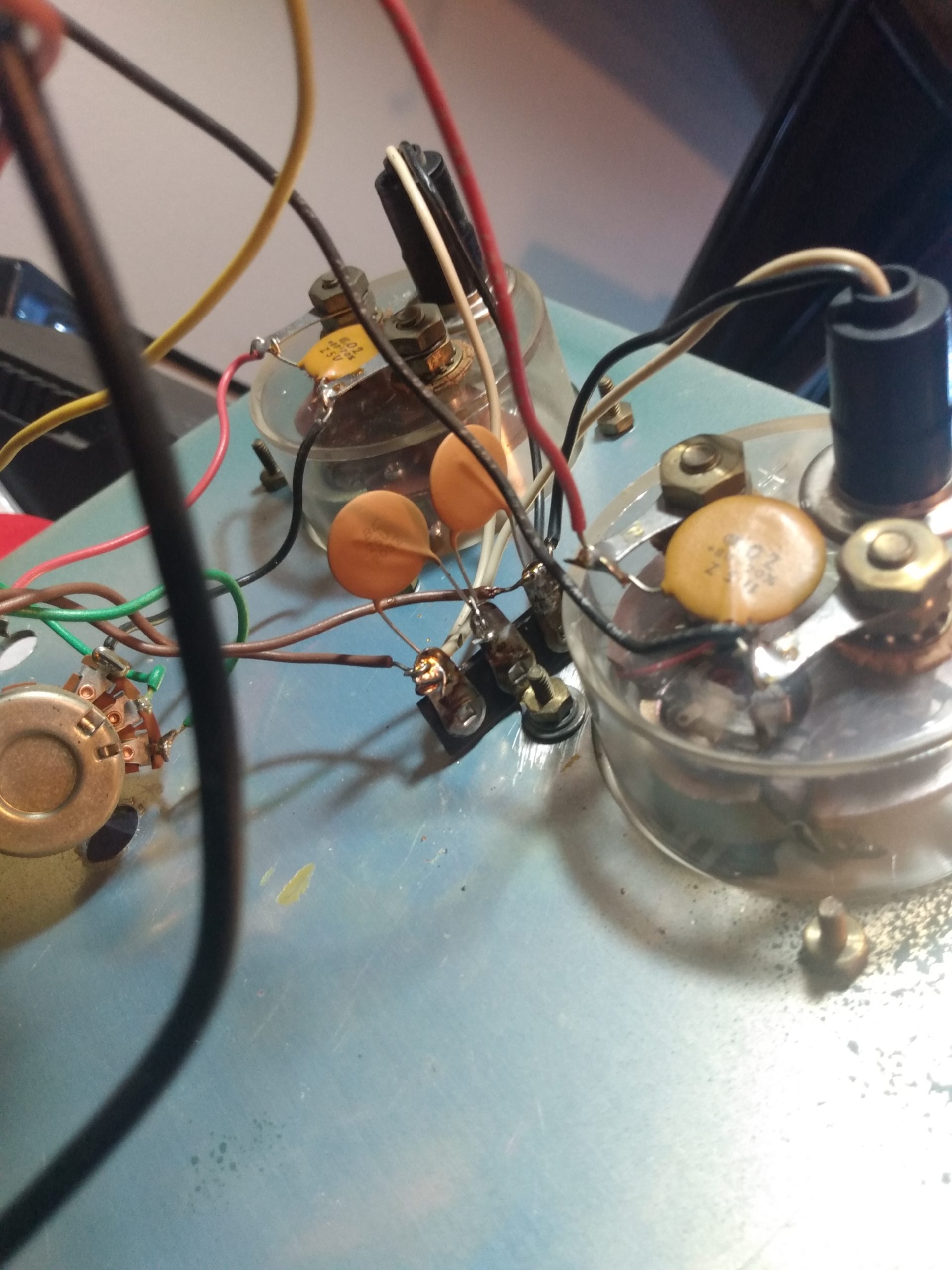
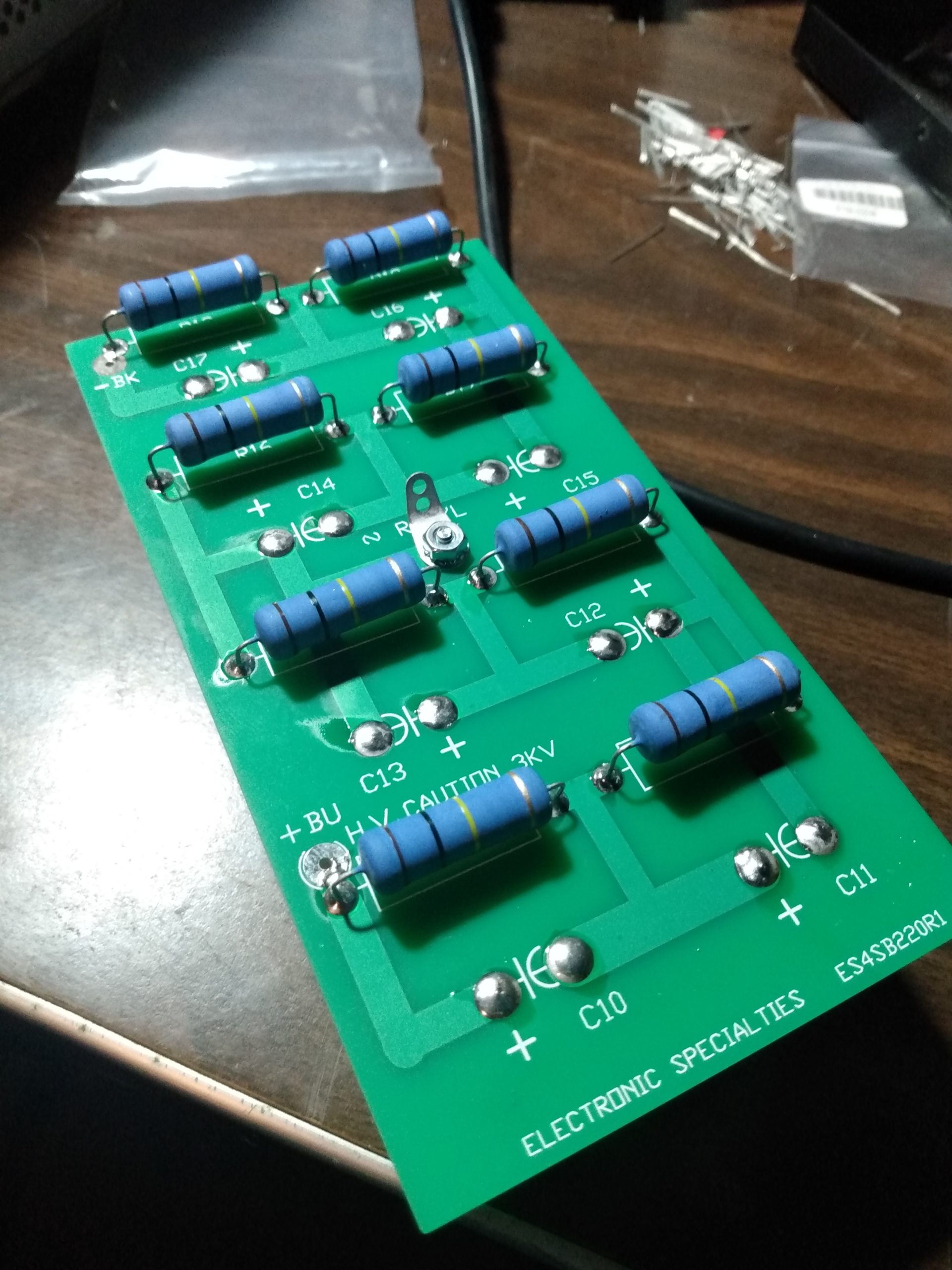
The filter capacitor bank contained the original plastic spacers, but the Nichicon capacitors and resistors did not appear to be original. I tested them and they all seemed to be within spec. Regardless, their age could not be confirmed so they would be replaced.
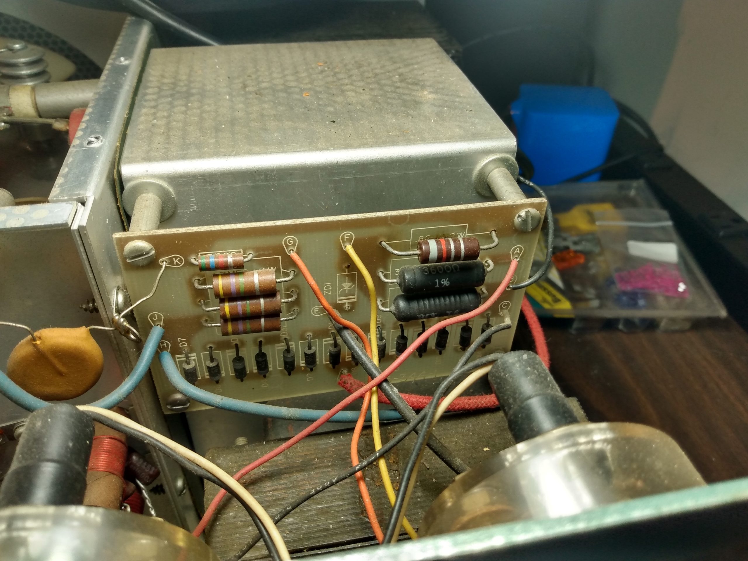
The rectifier/metering board and all components were original. There didn’t seem to be any issues with the board, and the meters did not appear to be modified with protection diodes. At this point I considered praying that the meters still worked. I wouldn’t know until I turned the amp on for the first time.
The input coils were in good shape, but the 20m coil did not look original. Not sure if it was replaced or if it was just built with different wire.
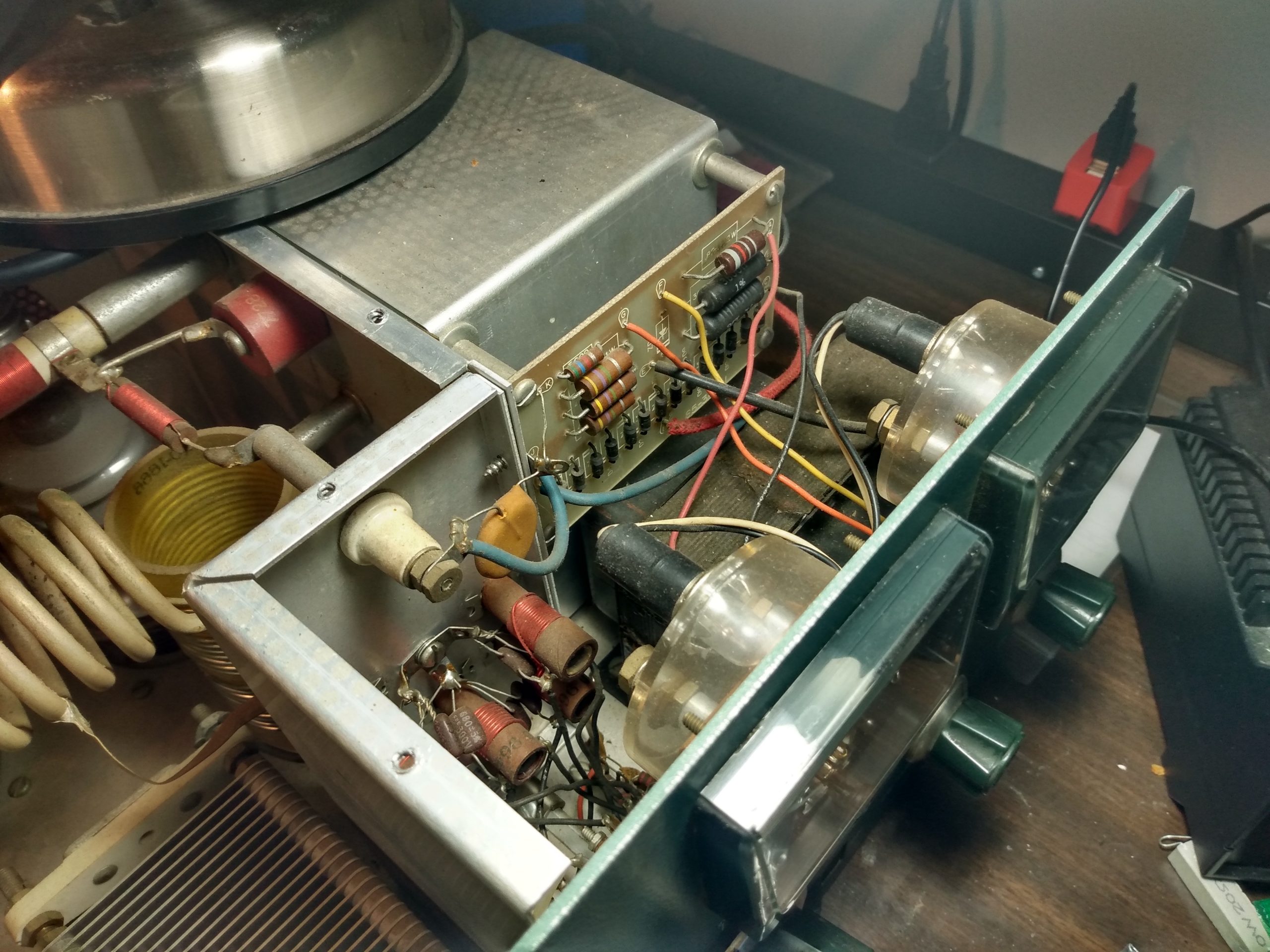
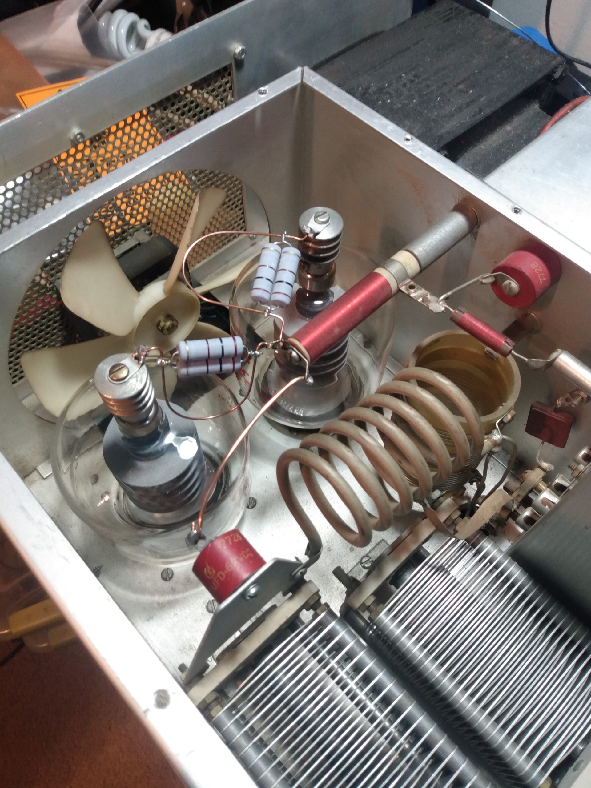
At first glance, or to the untrained eye, everything looks fine in the “tube chamber.” It wasn’t. There was a uniform amount of dust on all components, but this just meant that the amplifier hadn’t been messed with much lately. I erroneously took this as the amp being “unmolested.” I’ll go into more depth with this later.
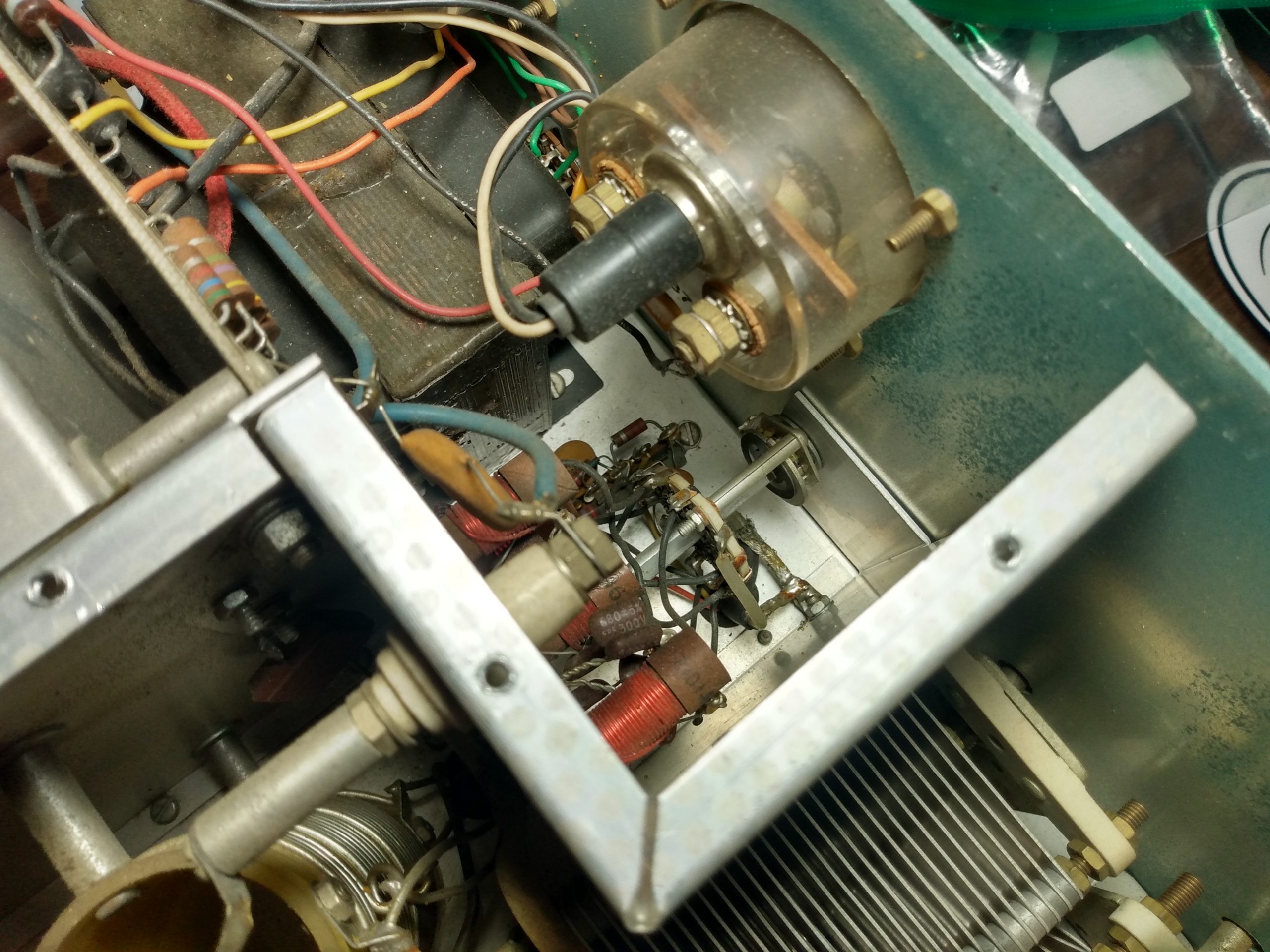
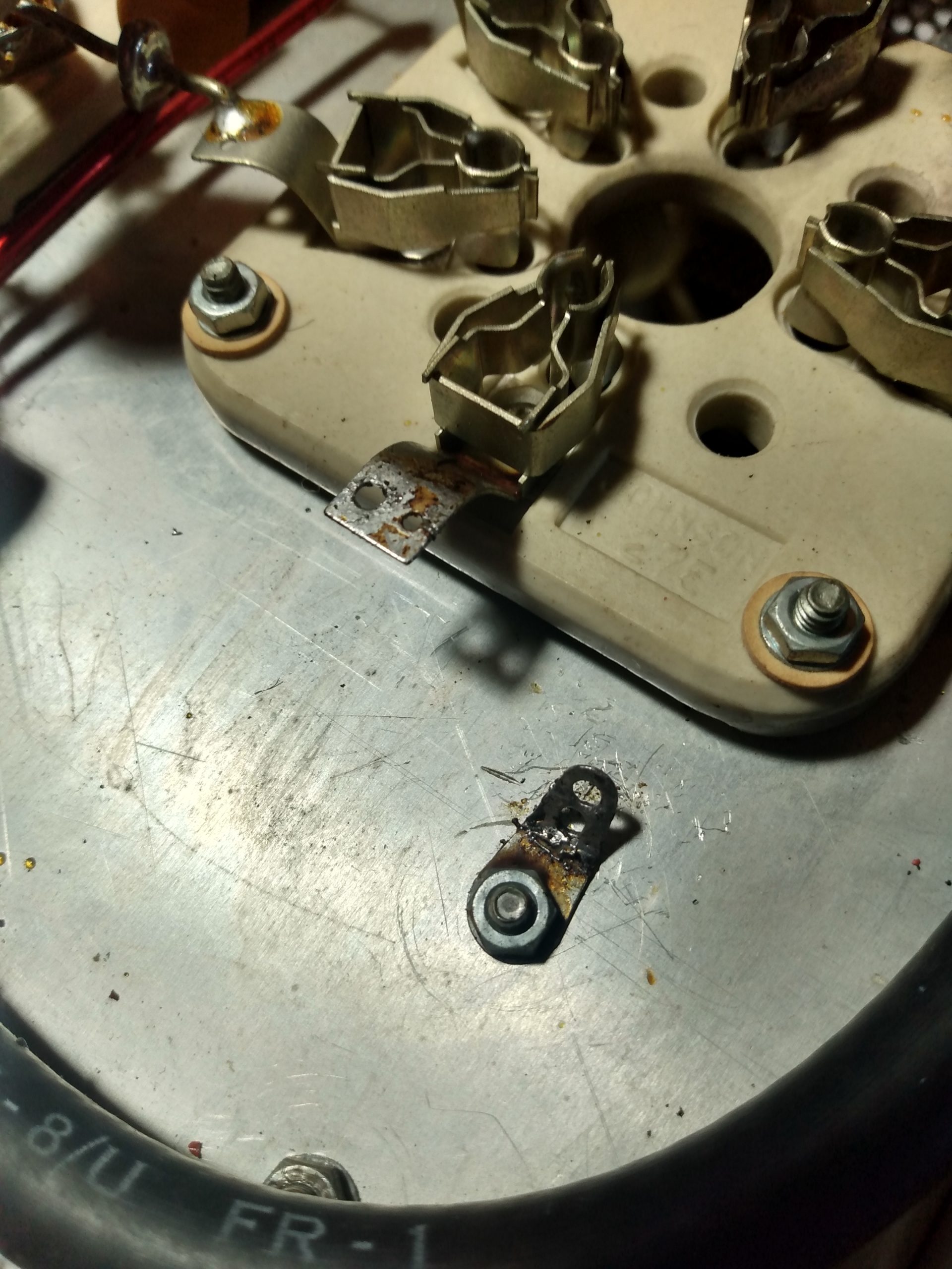
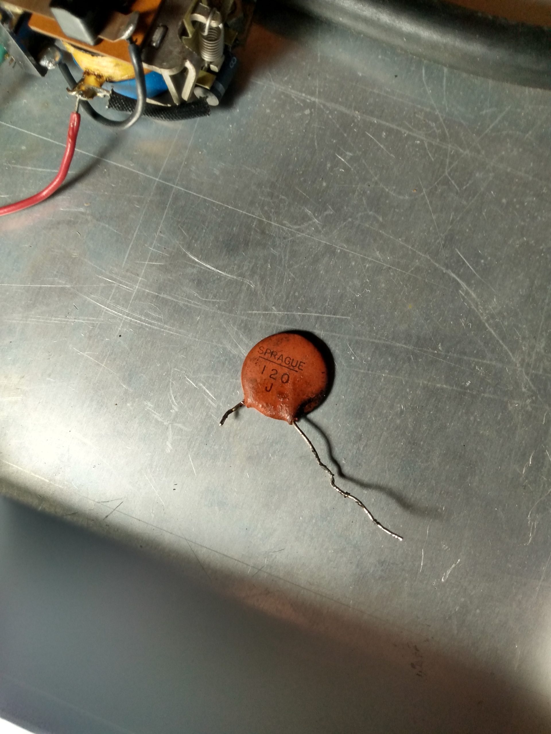
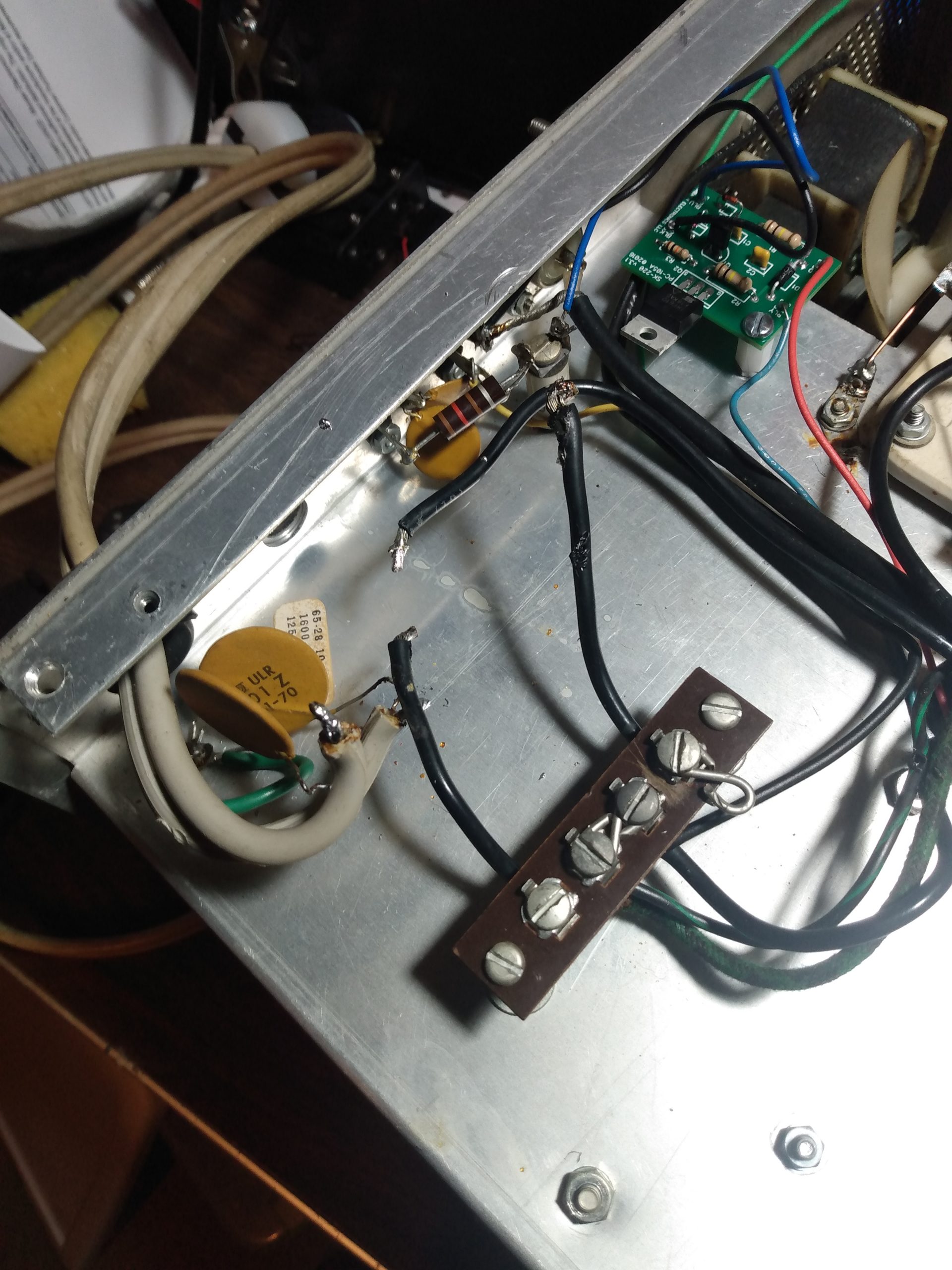
The guts of the SB-220 appeared fine at first. Digging in, a few things jumped out at me. There is a capacitor connected to a terminal leading to the 120v transformer that appeared to be replaced, and physically leaking. This capacitor is known to blow in case of tube flashover, so I marked it for replacement. This lead me to the grid connections on the tube sockets, which were not grounded. Grounding the grids on the SB-220 is considered best practice (explained later), so I added this to the todo list.
The fan was original, and it spun freely, which I’ve been told is unusual for this vintage. I decided to keep it, for now. Both transformers also appeared original and in good shape.


Preparations
Now that I had some idea of what I was dealing with, I laid out my objectives. I already had a working amplifier, an Ameritron AL-80A, that (after repairs) had proven itself pretty reliable loafing along at 500-600w. I like this amplifier and have no intention of selling it. But I wanted this SB-220 to be the new primary amplifier in my station, capable of running 1KW+ for extended periods of time on most bands, with all the modern upgrades that would extend its life for another 20+ years and allow it to be keyed by modern rigs.
The SB-220 came with a pair of Taylor 3-500ZG tubes, which are PRC reproductions of the venerable Eimac 3-500Z. I did not know what electrical state these tubes were in, but I didn’t want to replace them if I didn’t have to, so I removed them, cleaned them, and packaged them carefully for long term storage (note: tubes can be cleaned with isopropyl alcohol, but the alcohol will remove the logos). New matched 3-500ZG tubes run about $500, so I’d forego this cost if the tubes ended up being good.
Harbach Electronics makes several replacement board kits for the SB-220, and I opted to use all of them for this project:
- The RM-220 rectifier/meter board replaces the stock power board and is an improved design that also includes meter protection. As a result, the well-documented meter protection mod for the SB-220 that I planned on doing would not be required.
- The ES4SB220 filter board replaces the existing filtering capacitors and resistors and fits into the stock plastic spacers. The caps and resistors are rated higher than necessary for additional overhead and we are told they run cooler than stock, which is a good thing in an enclosure with tubes that generates a lot of heat.
- The 3-500Z is an “instant-on” tube, so the SS-221-240 soft-start board wasn’t 100% necessary. But inrush current can also negatively affect hard to find (and expensive) components such as Heathkit on/off and band switches, so it’s well worth the $35 to install this board. Quoting Harbach Electronics: “The SS-221 limits inrush current during amplifier start-up by placing a small resistive load in series with the AC mains. The load is switched out of the circuit by the relays a few milliseconds later.”
- Back in the 70s when this amplifier was designed, it was keyed by a boat anchor radio via 120VDC. Trying to key this amplifier with a modern transceiver would damage the transceiver’s keying circuit, and possibly other parts of the radio. The SK-220 is a soft-key interface for the SB-220, allowing the amplifier transmit relay to be engaged with under 1VDC @ 1.5mA. This is a necessity.
SB-220 Restoration
Before building the new boards and installing them, there were a few things that needed to be addressed.
The plate tuning capacitor looked great at a glance. But closer inspection revealed that it had been arcing repeatedly, which had damaged the rotating blades. Only after removing the rotating blades from the capacitor did the extent of damage become apparent. I suspect that the capacitor arced once due to a bad tune, which deformed the tip of a blade, which changed the capacitance of the capacitor, changing the tuning, causing more arcing, repeating over and over again. Clearly it had been abused. It would have to be completely disassembled to be repaired.
I removed the blades from the main assembly, and found that roughly half of them had been damaged. I believed it could be salvaged by sanding and polishing each of the blades. First I sanded the deformed part of each blade on a flat surface with 220 grit sandpaper. Once the blades were again flat, each was polished with 0000 steel wool. There was only minor loss of material on some of the tips of the blades. You wouldn’t know unless you knew what to look for. The important detail is that now all the blades are straight and uniform thickness so they should mesh evenly.

I also disassembled the fixed blade assembly of the capacitor and found some neat squiggly electriciy drawings, and some damage to a few blades. These were sanded and polished in a similar fashion, but the damage was minor in comparison to the rotating blades.
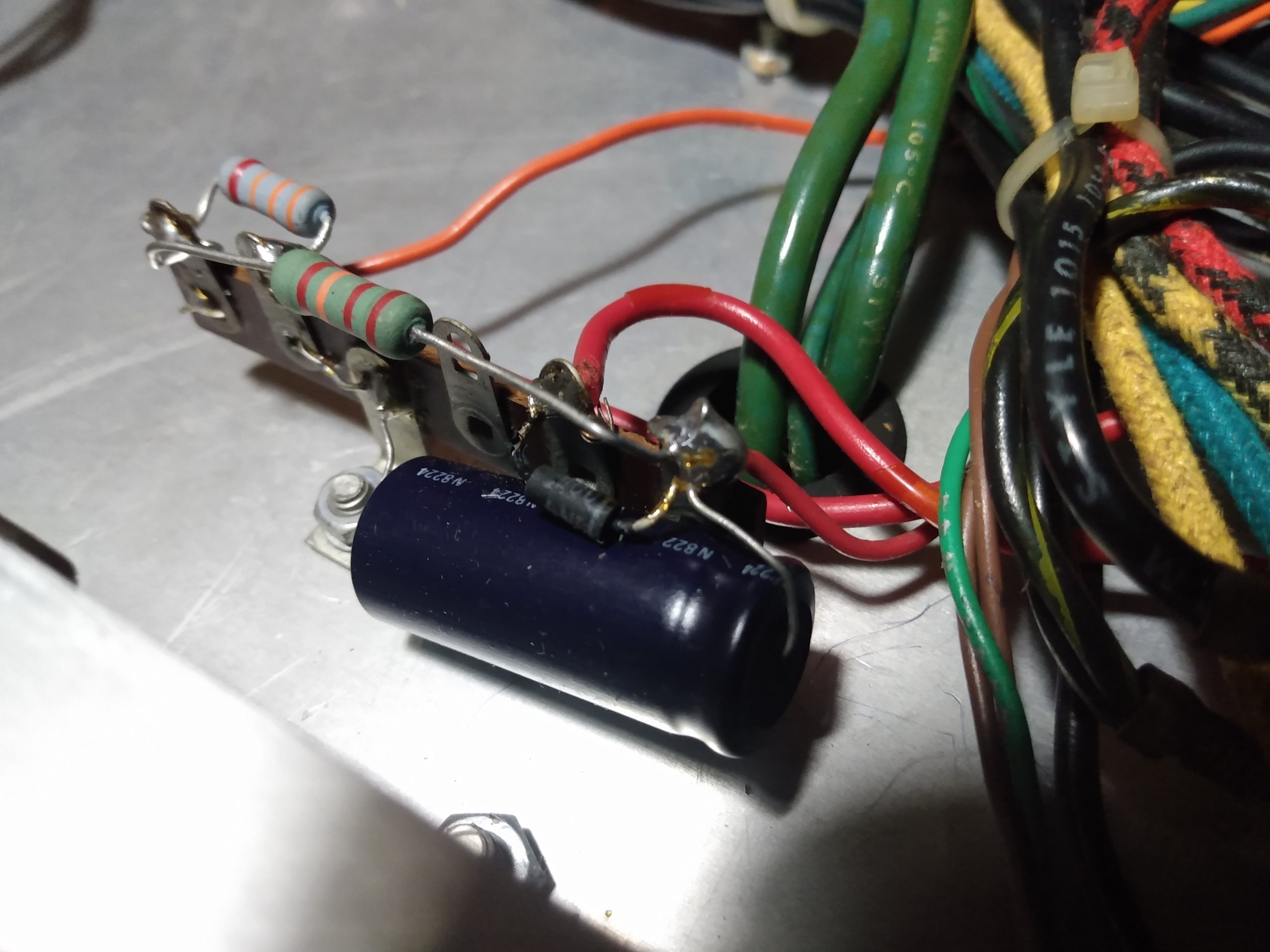
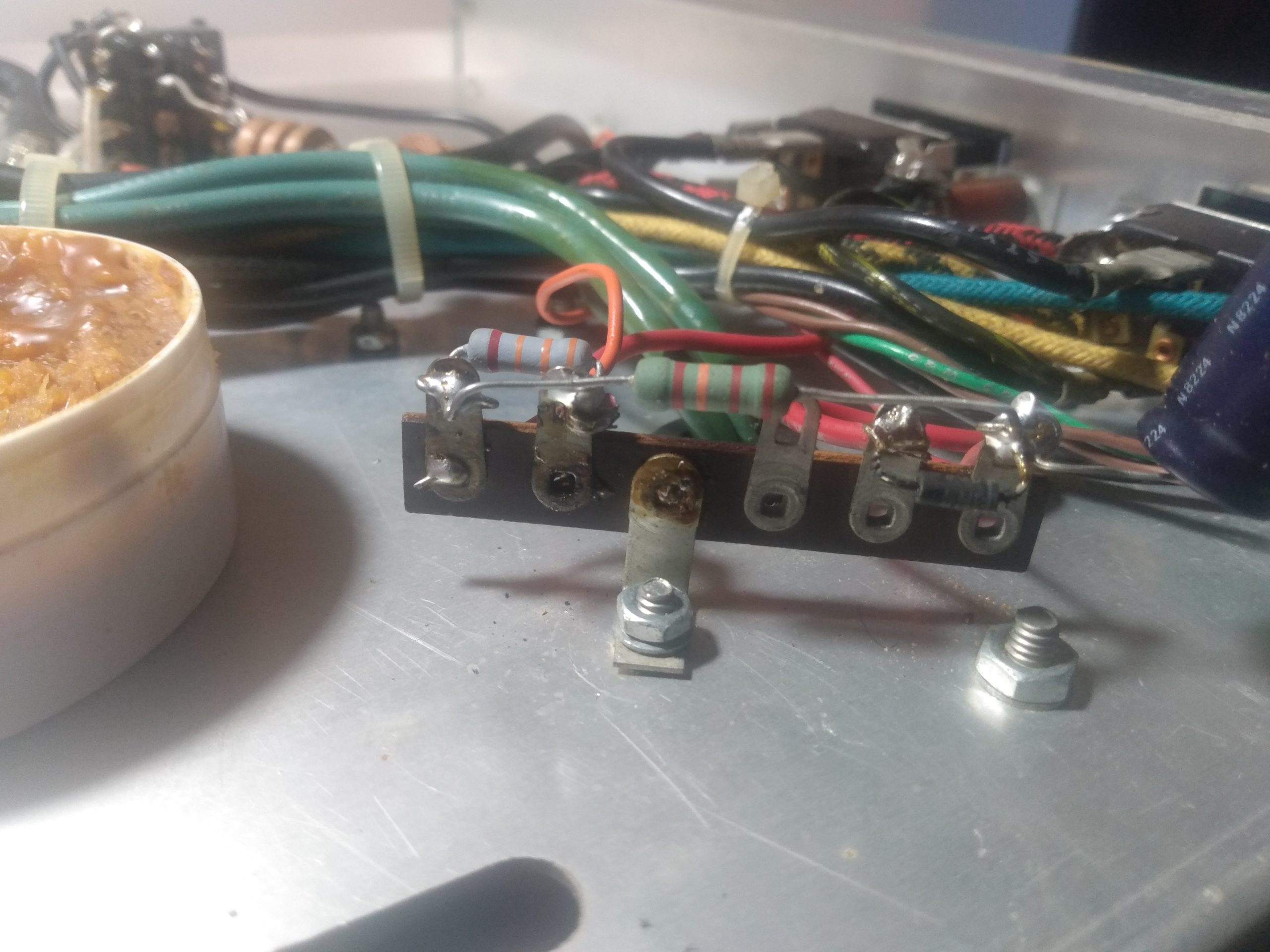
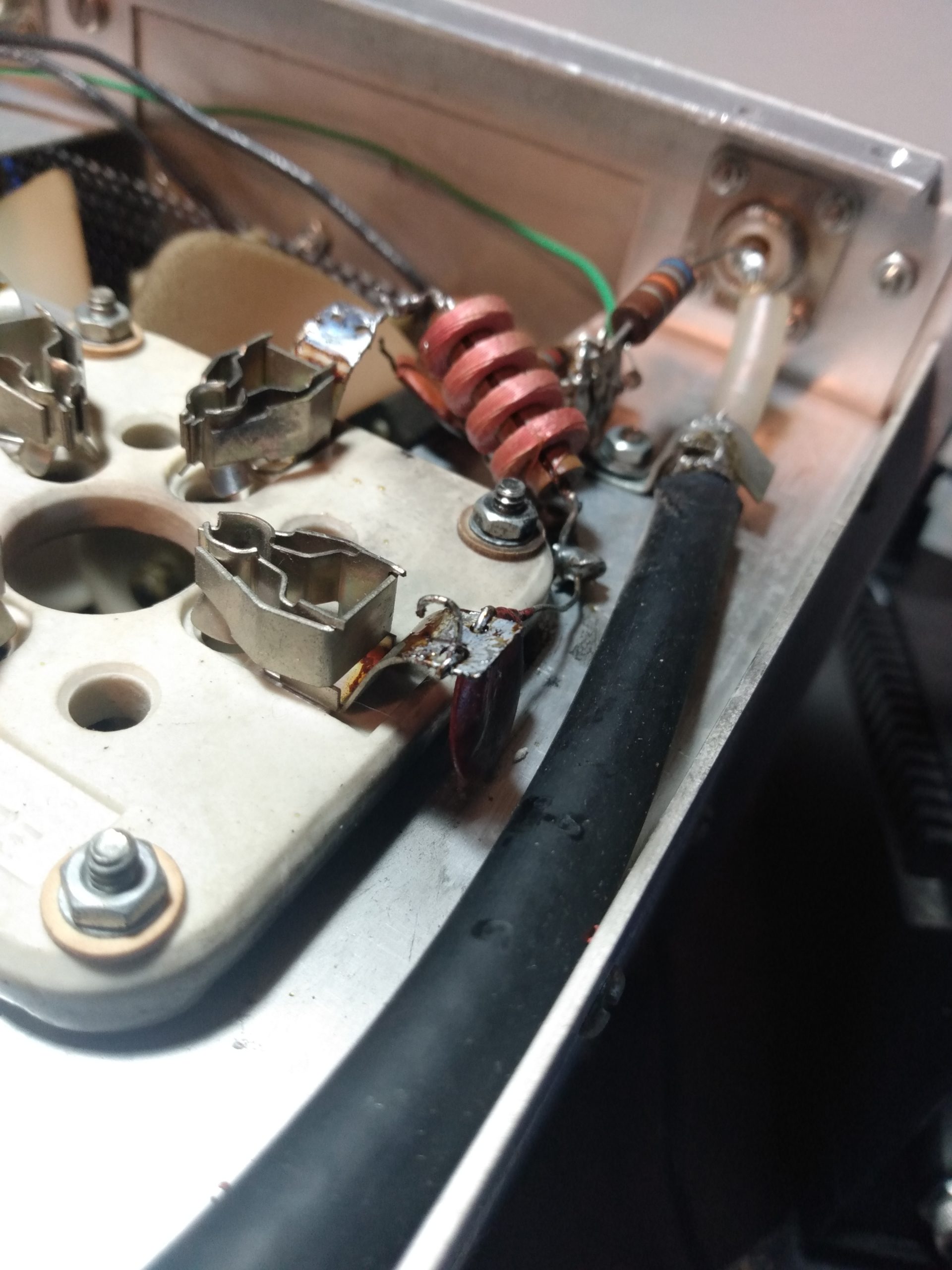
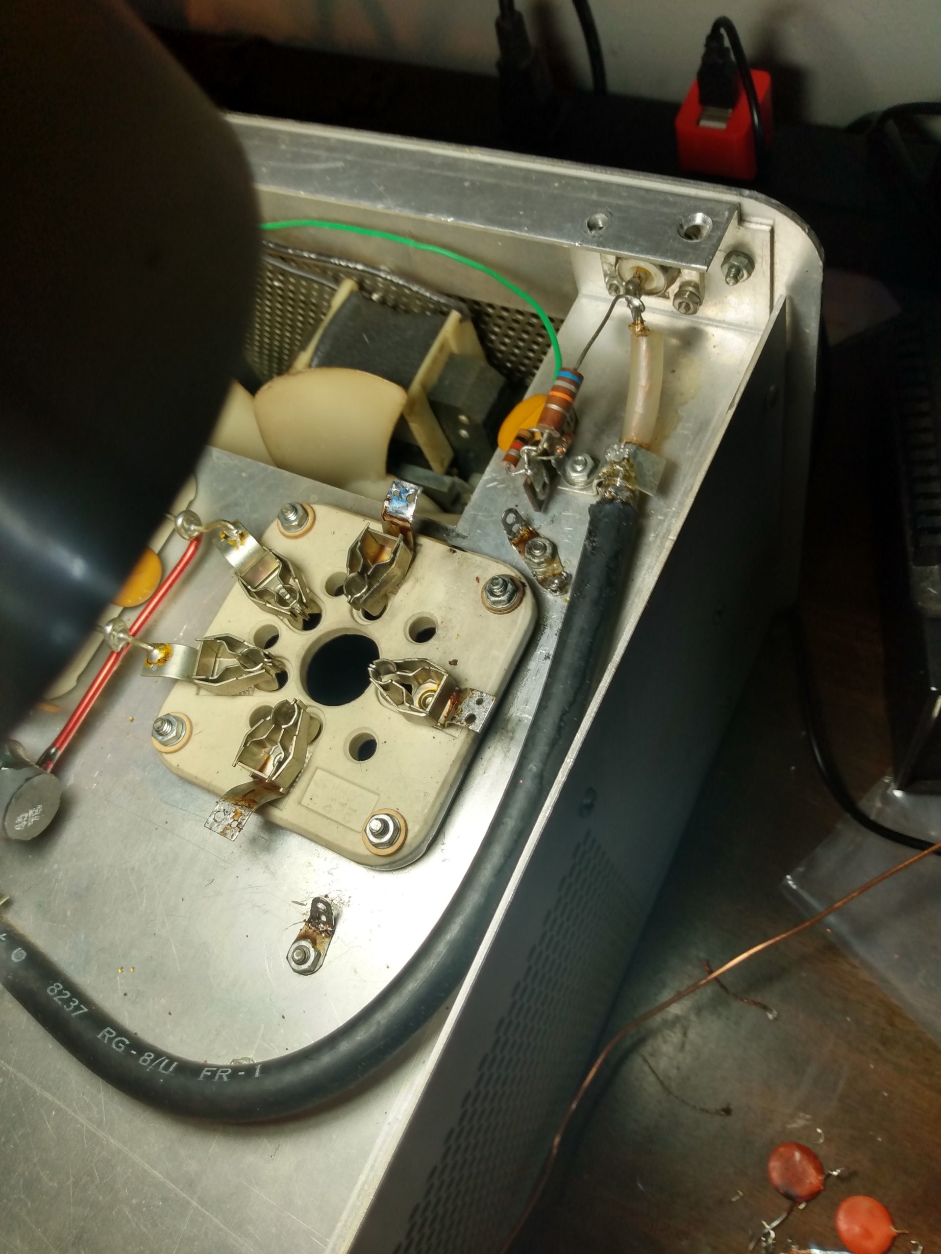
I knew enough about 3-500Z amplifiers to know that these parasitic suppressors were not original, which didn’t concern me. But the fact that these suppressors were not soldered DID concern me. The leads of the resistor were just wrapped around the bent wire, free to slide around. There was evidence of arcing on the side of at least one of these resistors. And the suppressors themselves were not soldered to the lugs on the coil (despite these lugs being present), instead they were wrapped around the screw and held in place by friction. These would have to be replaced.
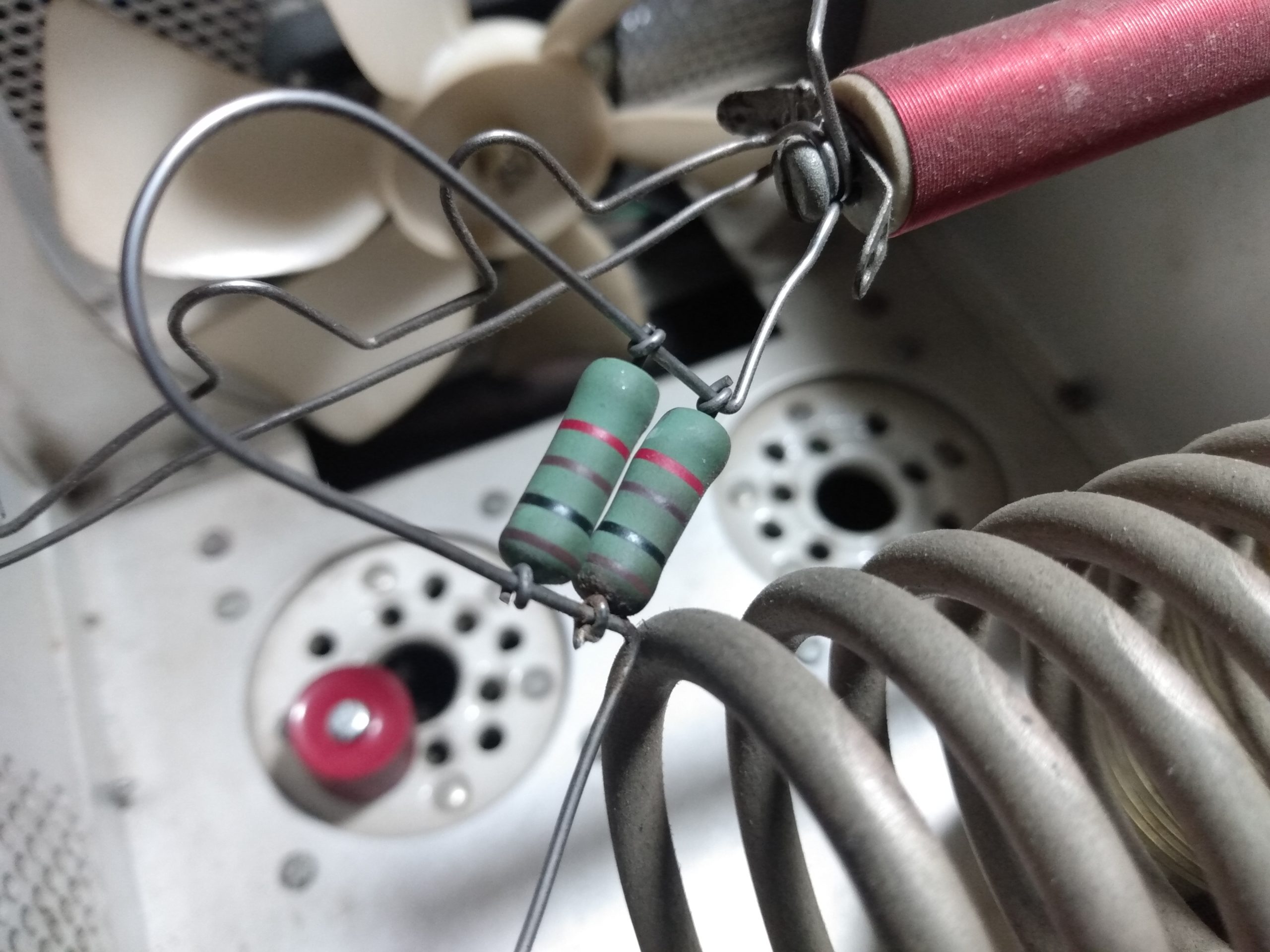
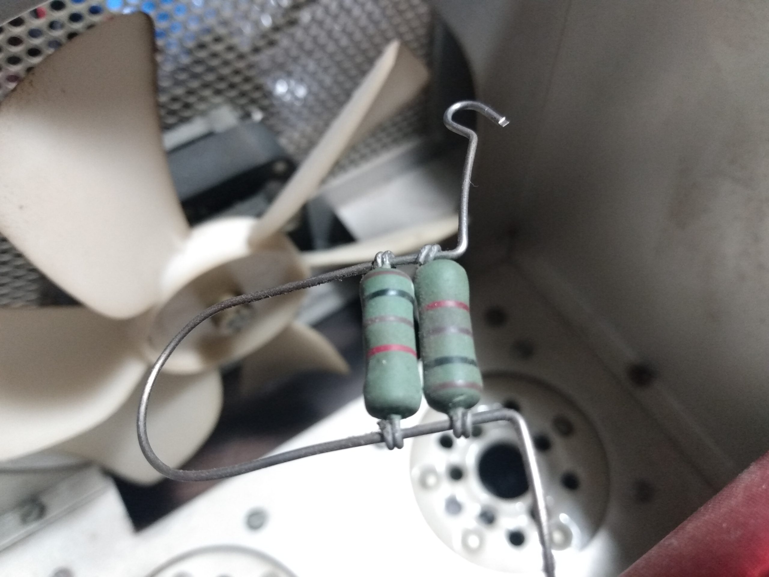
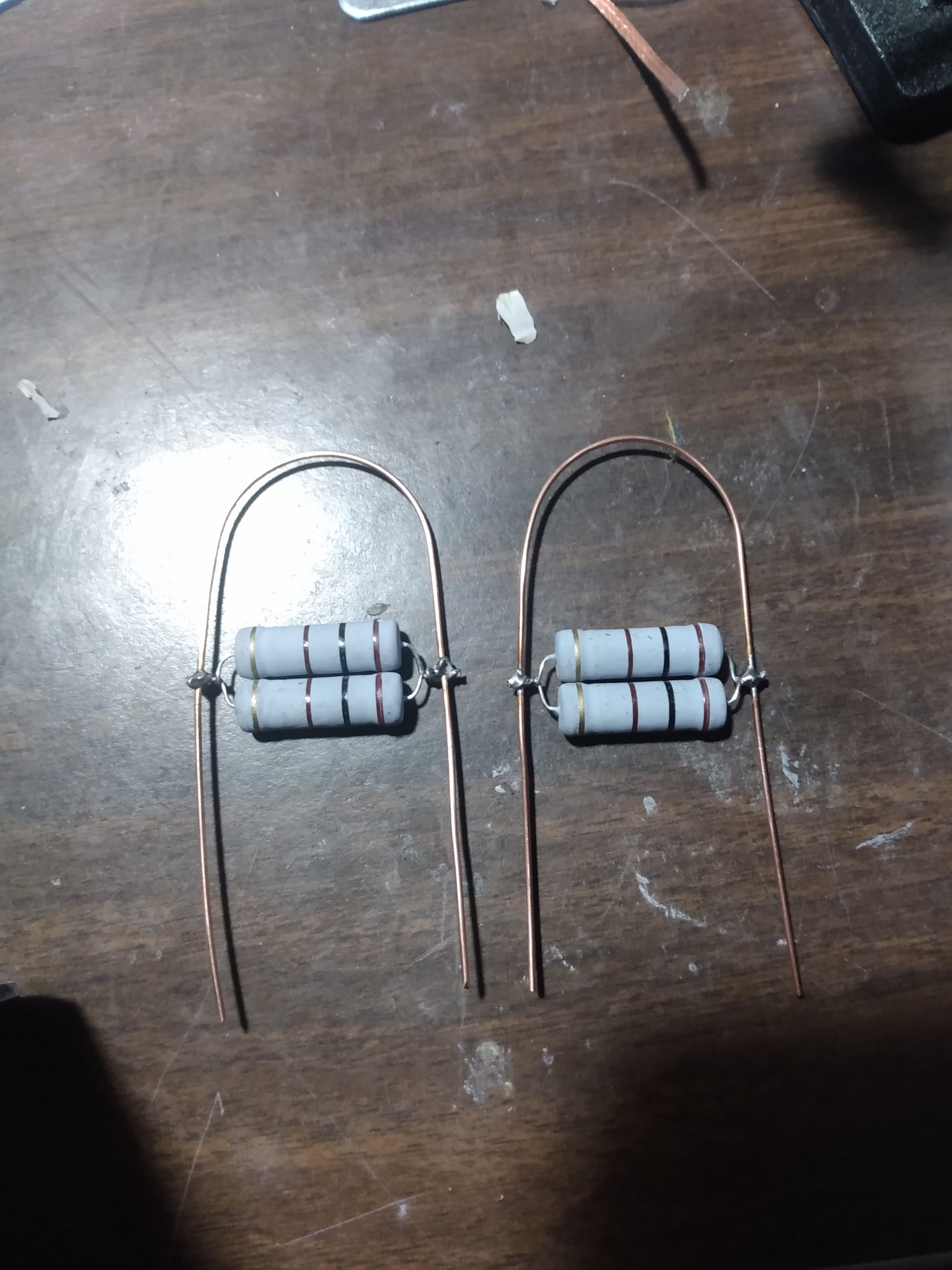
I built new parasitic suppressors with 18 gauge copper wire and 100 ohm 5 watt resistors, making sure to solder the connections between resistors and wire. These would not be installed until the tubes were back in their sockets, so I set them aside.
It was time to remove the original power board and filter capacitor bank, which would both be replaced by the modern Harbach kits. The capacitor bank is held in place by bolts on the bottom of the amplifier, some of which are hard to get to due to existing wiring, so rather than remove the capacitor bank completely, I just loosened those bolts enough that I could cut the leads connecting the capacitors and remove them. I took great care to not damage the original plastic spacers that hold the capacitors in place, they would be reused with the new kit.
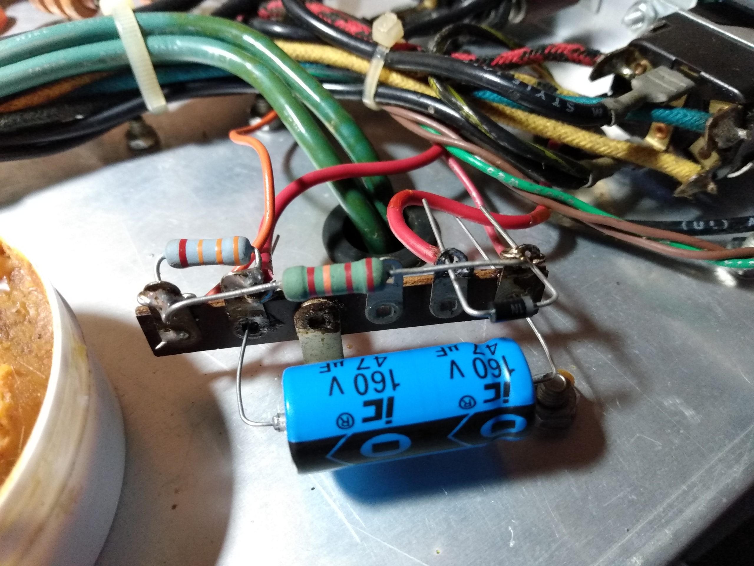
With the old capacitor bank removed, I took out the screws holding the faceplate to the front of the amplifier and swung it to the right of the case to begin removing the original power board. There were also some structural components removed to do this, those were set aside for eventual reassembly. During desoldering and removal of the power board, I noticed that one of the two capacitors on the meter lamp circuit had failed catastrophically. The capacitor had blown hard enough to leave a residue on the back of the faceplate. I’m not sure what could have caused this, and I crossed my fingers that it hadn’t caused damage that I couldn’t see. Parts were ordered, and both the blown capacitor and its original unscathed companion were replaced with new components.


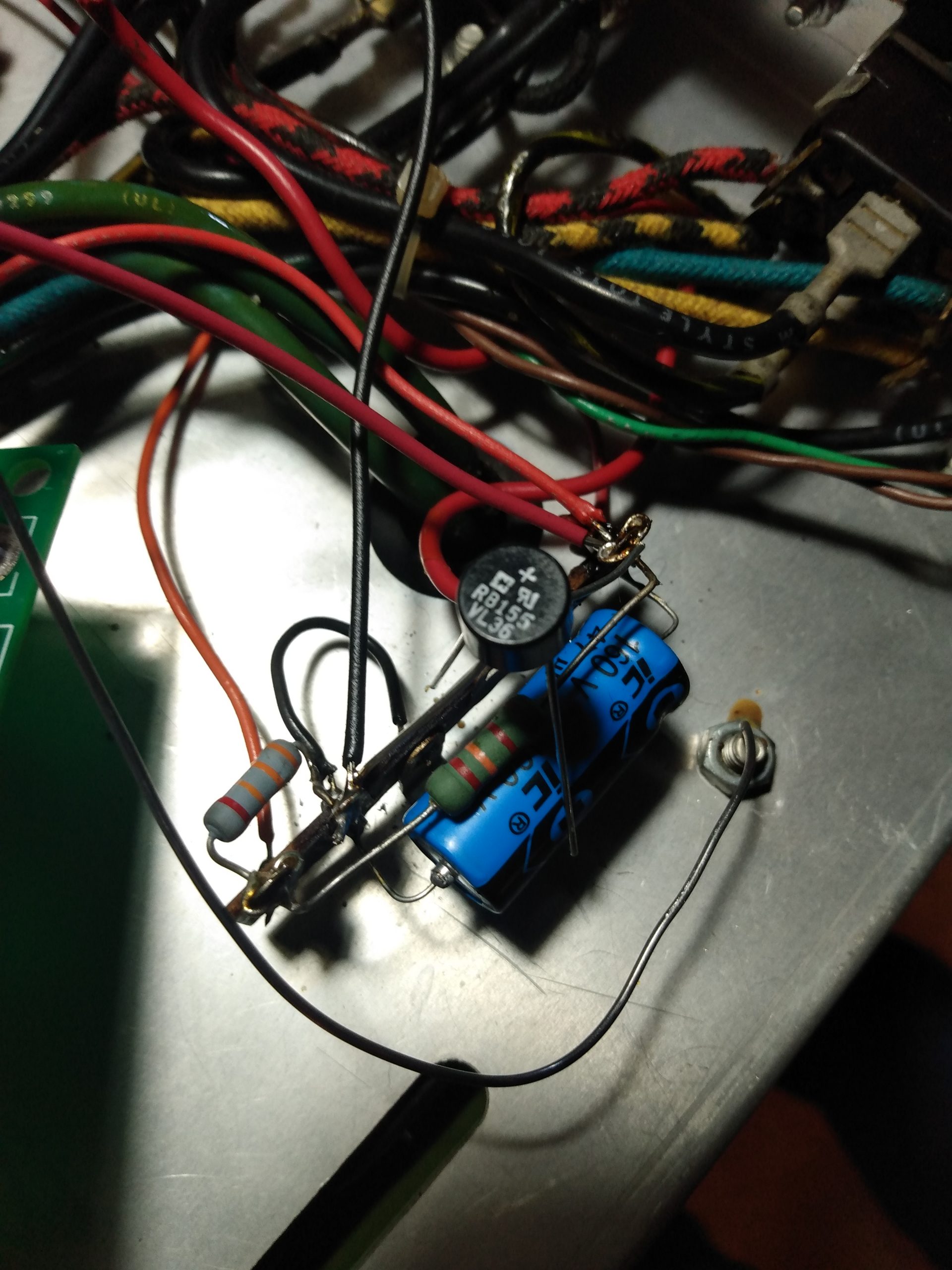
At this point I replaced that leaky capacitor attached to the 120v transformer. I had seen this capacitor referenced as one of the first components to release the magic smoke during a tube flashover, so I paid special attention to it. The fact that it had some discoloration around the negative terminal spoke to the possibility that it had experienced some abuse, so it seemed a smart move to replace it. While doing so, I managed to snap the attached diode in half, so that was replaced as well. This was a simple job, but I did not realize that I would be removing that diode during the install of the Harbach soft key board in the near future anyway.
With the problem areas of the SB-220 taken care of, it was time to focus my efforts on the upgrades and modifications necessary to modernize this amplifier.
SB-220 Upgrades and Modifications
My next step was to flip the amplifier over and begin removing the stock grid circuitry on the tube sockets. I have heard Heathkit in its early days described as “bean counters designing amplifiers,” which might explain some design decisions. But why remove all these components just to ground the grids? I’ll let W8JI explain, because I can’t:
“The grid not only shields the input from direct RF feedback from the anode,
-W8JI, https://new.w8ji.com/grounded-grid-amplifiers/
it is also a good shield to prevent or minimize the anode voltage that might
appear on the cathode during tube arcs. Floating the grid above ground is bad
for RF, and bad for arc protection.”

Whoever built this SB-220 back in the 1970s did a good job. In fact, they did such a good job that I used almost an entire spool of solder wick getting the grid circuitry removed from the terminals and ground lugs. Not a single component lead had been clipped after soldering. Instead, the lead was wrapped around the terminal, up to 3 times, and completely covered with solder. The desoldering and removal process took well over an hour, and the grounding process took about 10 minutes. I used the same 18 gauge solid copper wire for grounding that I used to build the new parasitic suppressors for the tubes.
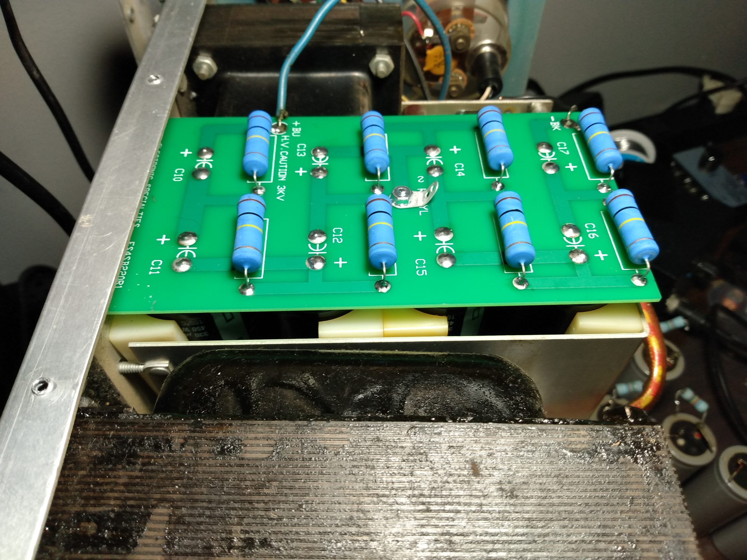
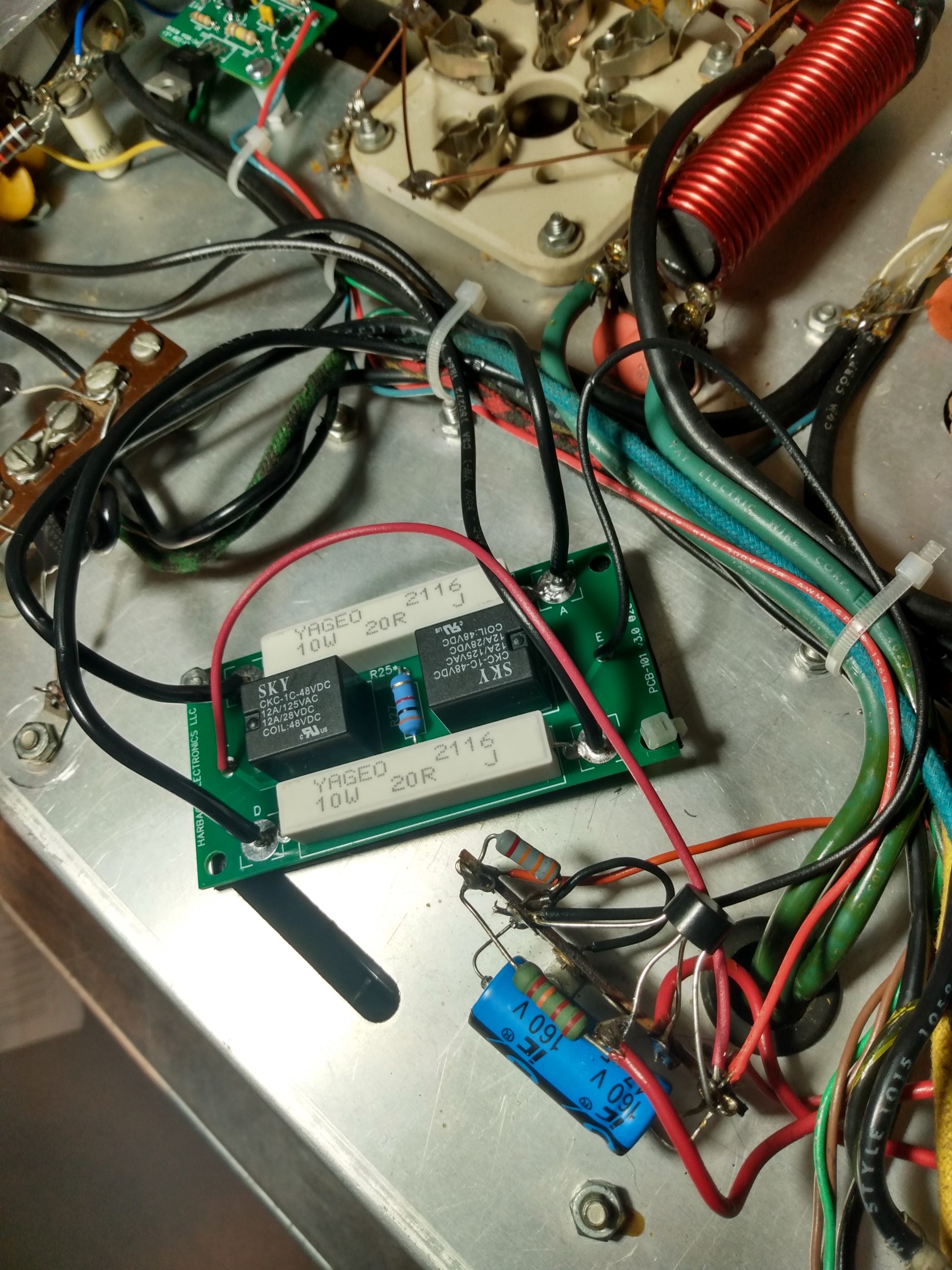
It was time to start putting the amplifier back together. I had built the new Harbach boards as soon as they arrived so they would be ready whenever I needed them. First to go in was the filter board. This board utilized the original plastic capacitor spacers. At first I tried to install the board using only 4 of the spacers, but I was not satisfied with this because the capacitors seemed to stress their connections to the board under their own weight (the board mounts vertically). I decided it was best to use all of the spacers, which took more time to shoehorn into the enclosure, but all the capacitors are securely in place and will not stress their solder joints. I left some space between the bottom of the capacitors and the board itself during its assembly to allow for better airflow and cooling.
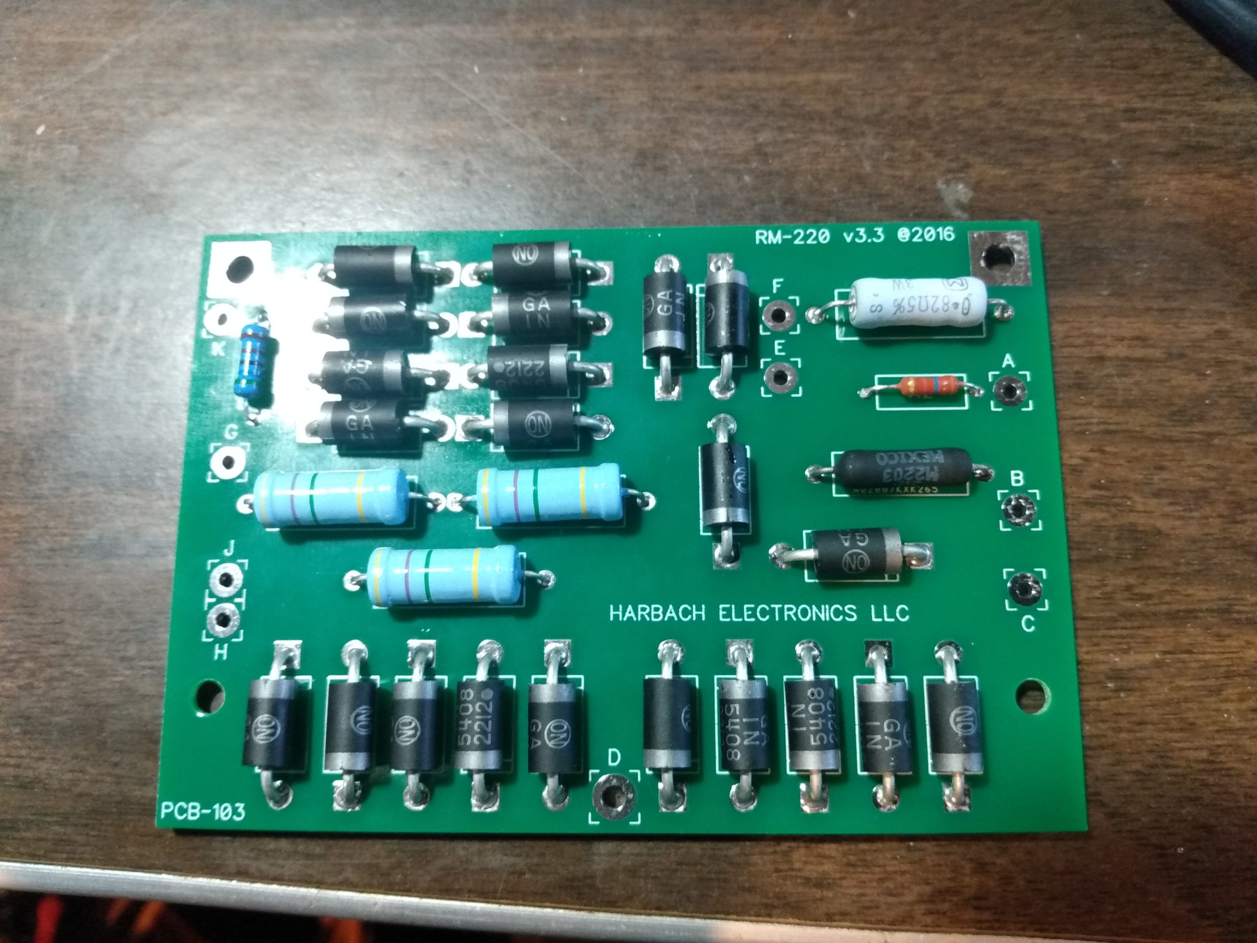

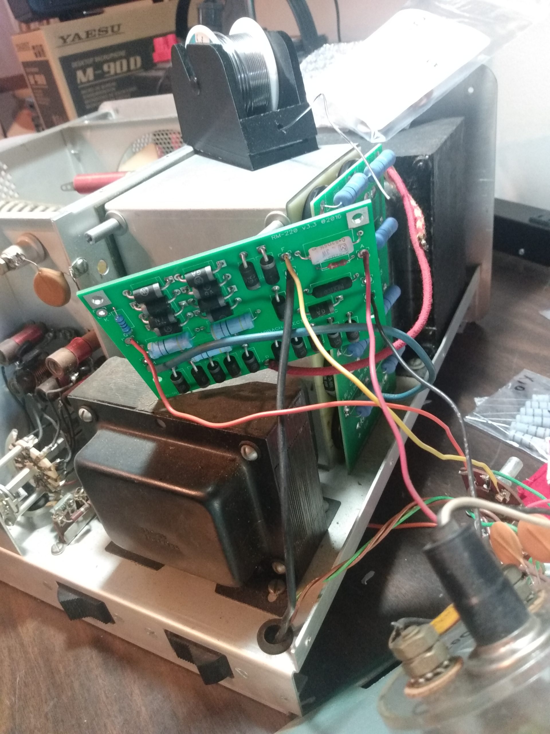
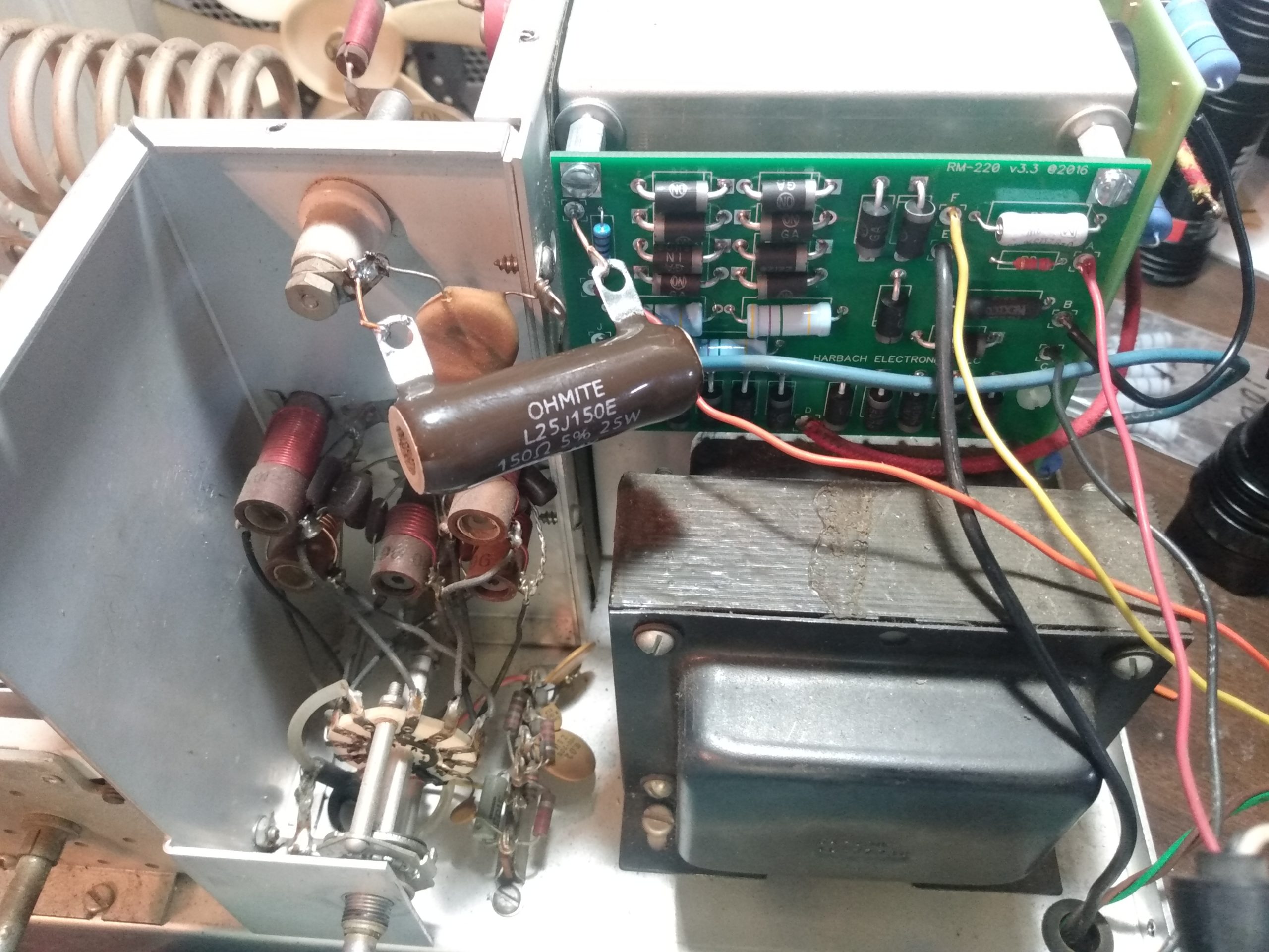
Installation of the power board is pretty straightforward and simple because all wire leads to and from the high voltage transformer and the meters were all their original colors, so it was a matter of stepping down a checklist to connect these leads to the new board. I also installed a 150 ohm 25w “glitch resistor” on the HV connection to the tubes, which is an additional protection in case of filament to grid shorts. You might notice that this is wired improperly in the photo. I also noticed this, thankfully. The error was quickly resolved and the board was wired correctly before faceplate reinstallation.
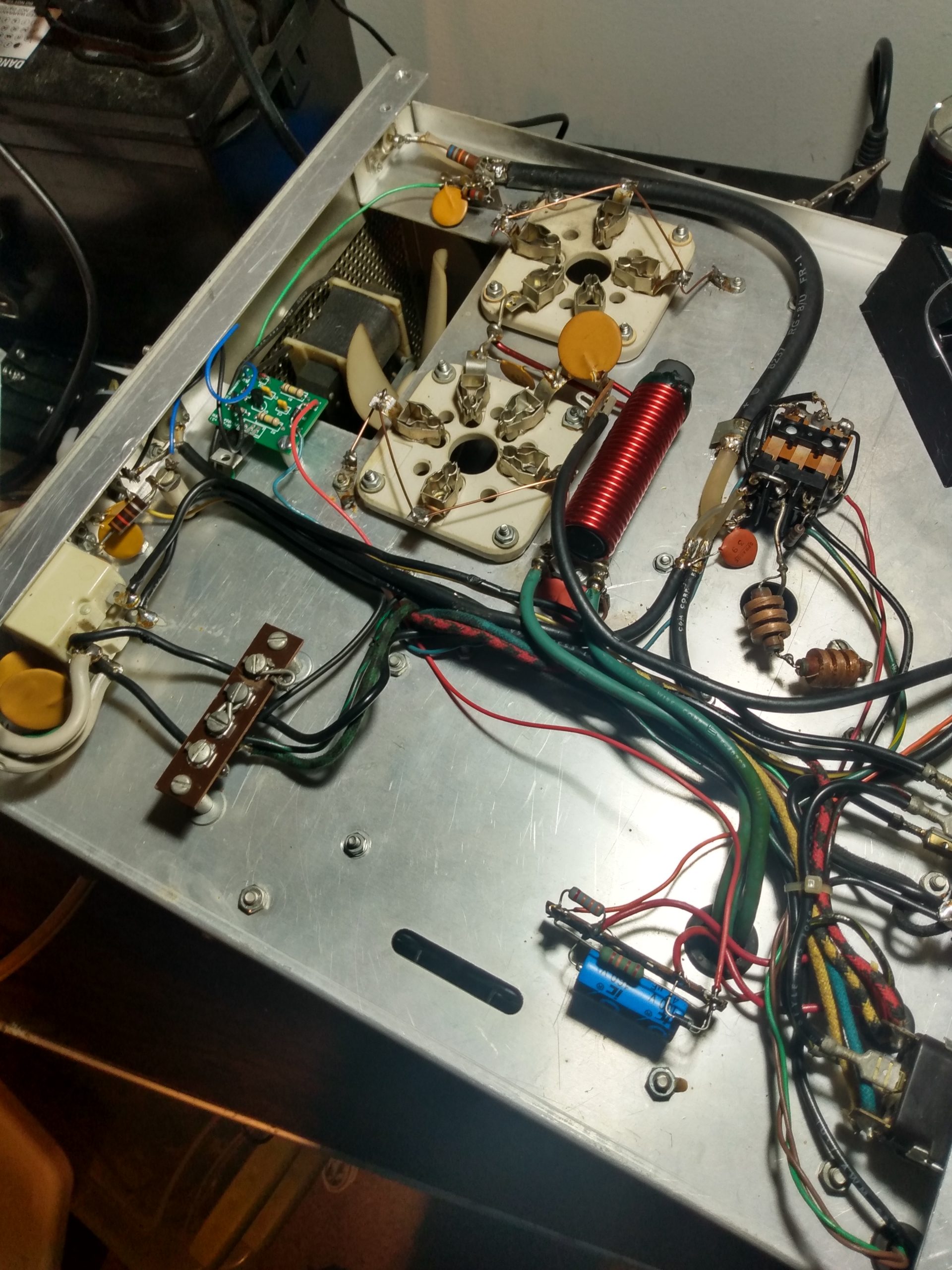
Once again, it was time to flip the amplifier over, this time to install the soft key and soft start boards. There were several things that had to happen in a specific order for this to be successful. First, I had to get the boards mounted in place. Second, I had to replace the original AC circuit breakers with modern replacements. Third, all of these pieces had to be correctly wired to each other. Little did I know that I was signing myself up for an entire day of work for this part of the job.
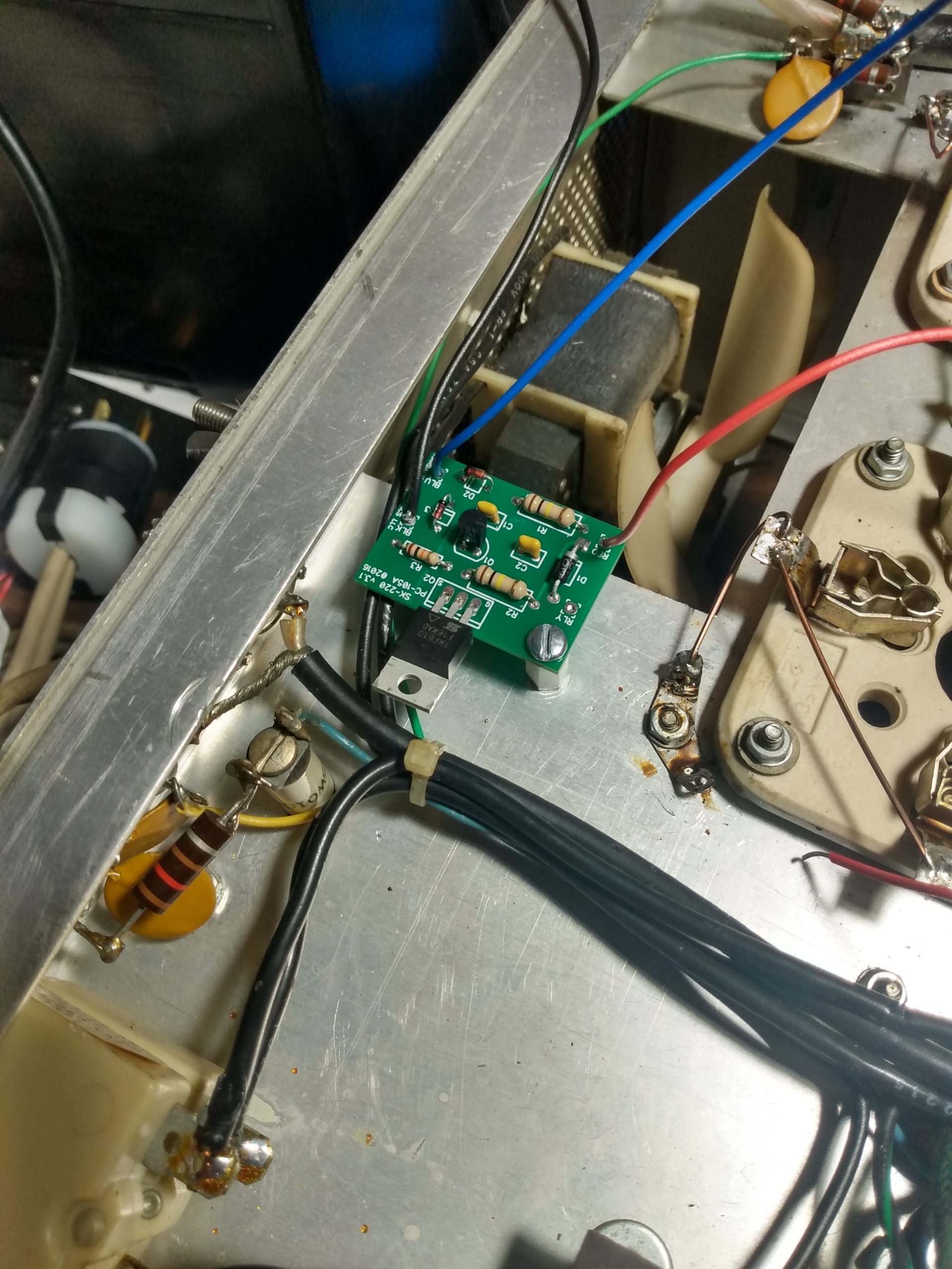
First was the mounting of the soft key board. This was the easiest step, a mounting lug was provided and there was an unused chassis mounting bolt under the fan dedicated to this. So I mounted the soft key board and soldered the leads to their corresponding terminals, not knowing I’d be undoing this as part of the soft start board installation. Always read the full documentation before soldering.
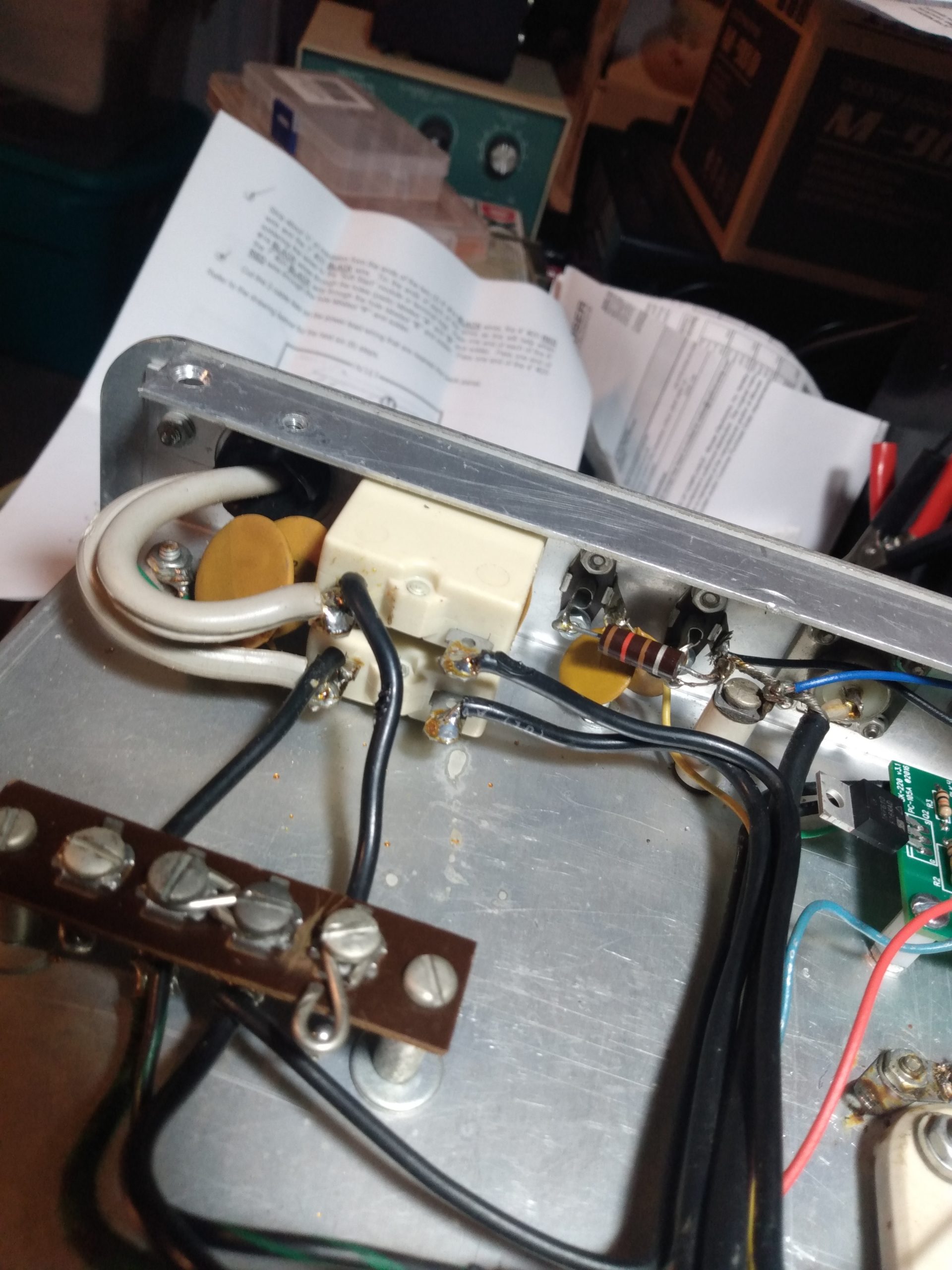
Next was removal of the original AC circuit breakers. This was as frustrating as the removal of the grid circuitry, for the exact same reasons. Lots of solder was used in the original construction, and two capacitor leads were securely wrapped around the solder lugs. All of this, in a more confined space than the tube grid circuitry. Lots of big words were uttered.

It was at this point that I ran into a new challenge. While the Harbach soft key board came with a lug to mount the board to the amplifier chassis, the Harbach soft start board did not, and I didn’t have anything similar to mount it. So I would have to find another solution.
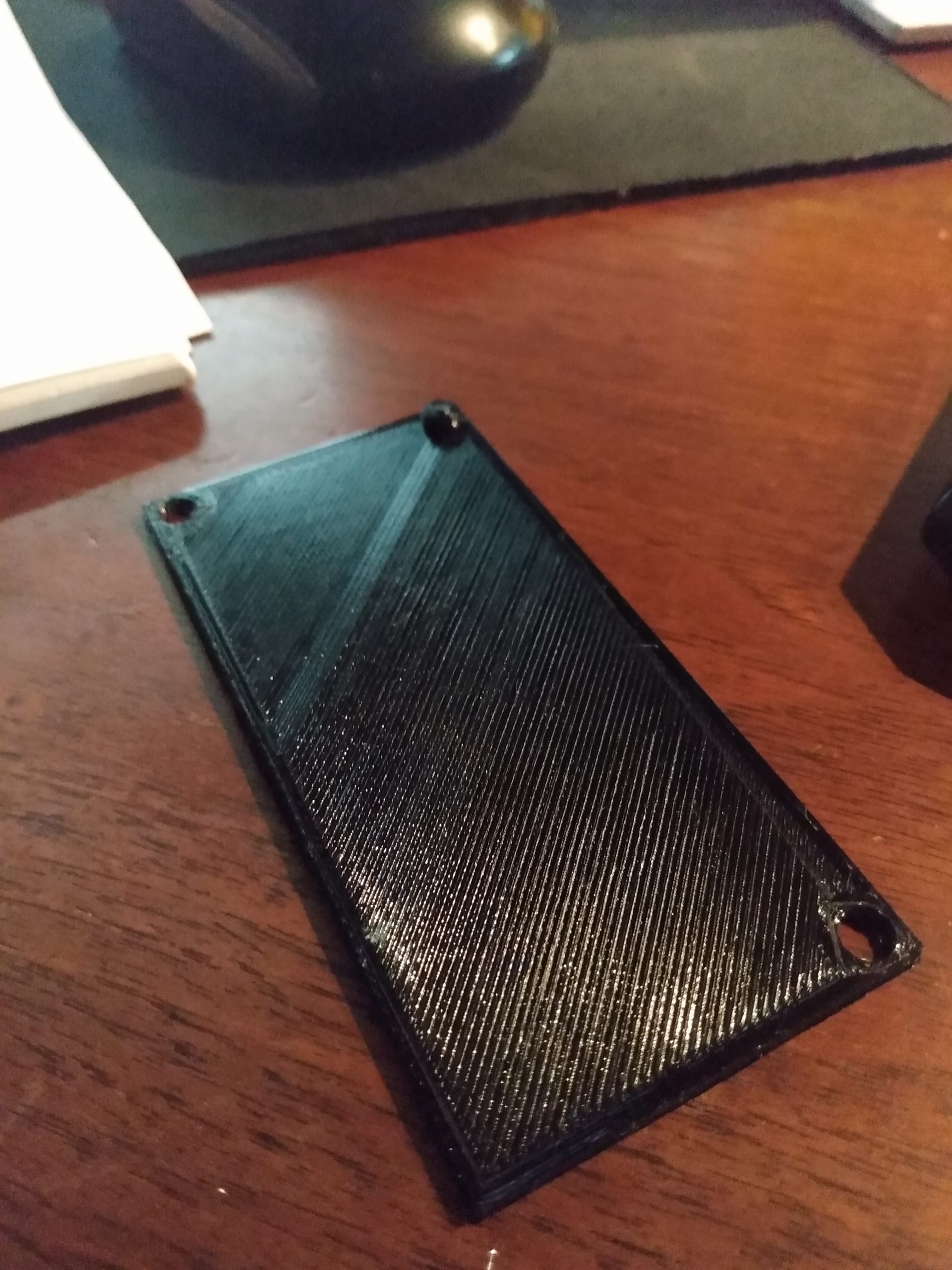
There is an “unused” bolt and nut between the AC terminal strip and the strip that connects to the 120v transformer, which is used to hold the capacitor bank in place. This is a suitable location for the soft start board, but it’s the only mounting point. Could I mount the board at only one point, and still prevent the board from moving around or shorting on the chassis?
I measured the dimensions of the board and location of its mounting holes, designed a 1mm thick platform in Tinkercad, and 3d printed it using PETG. The platform has a notch on one of the corners that fits into an existing slot on the SB-220 chassis. One hole in the platform is for the mounting screw/bolt, another hole for a zip tie to hold the board in place over its platform, and the notch fits into the slot in the chassis, using the tension of the wires to the AC breakers keep the soft start board in place. It’s securely mounted and the remaining connections are ready to be wired up. Two diodes were wired in series on the transmit relay at this point as well.
Finally the day has arrived, it’s time to put the tubes back in their sockets and complete the SB-220 restoration. At this point it was almost three months to the day since I brought it home. Taking care to not get fingerprints all over the tubes or damage them in any way, they were inserted into their sockets, new lugs screwed to the anode caps, and the newly built parasitic suppressors were soldered into place.
I am not confident enough in my abilities to not kill myself with high voltage, so I decided it was best to put the amplifier back into its enclosure before powering it on. This also meant that in the event that something was wrong, I’d have to disassemble it again to get back into it. Being frustrated is better than being dead, so I spent about an hour putting the top cover back on and doing the required yoga to get the chassis back into its enclosure. It wouldn’t be so difficult if it wasn’t for the fact that the chassis weighs about 50lbs and has to float at precisely the correct position within the enclosure for the 4 plastic feet to screw perfectly into their threaded holes. I do not look forward to doing this again.
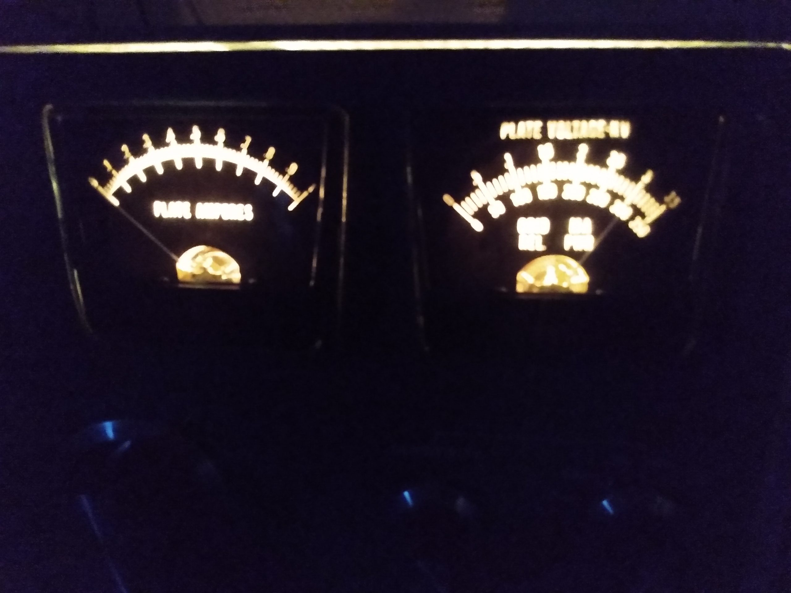
I ran a 240v extension cord from the outlet at my operating position over to the workbench. Then I spent 15 minutes pondering before hitting the switch. Would it turn on? Would it stay on? How much smoke would it give up? How loud would the tube explosion be? How do I explain it to the fire department? I finally grew a pair and hit the switch, and much to my surprise, the fan spun up, the meters lit, and the HV meter shot up to 3100v. Success!
More Modifications
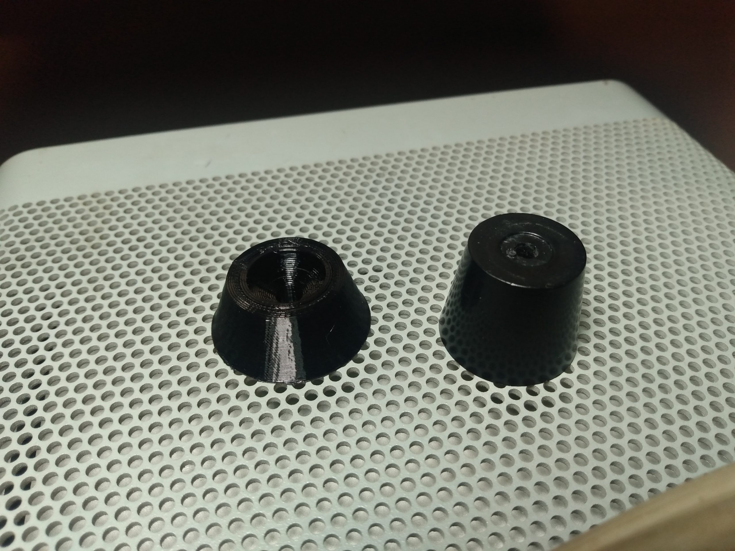
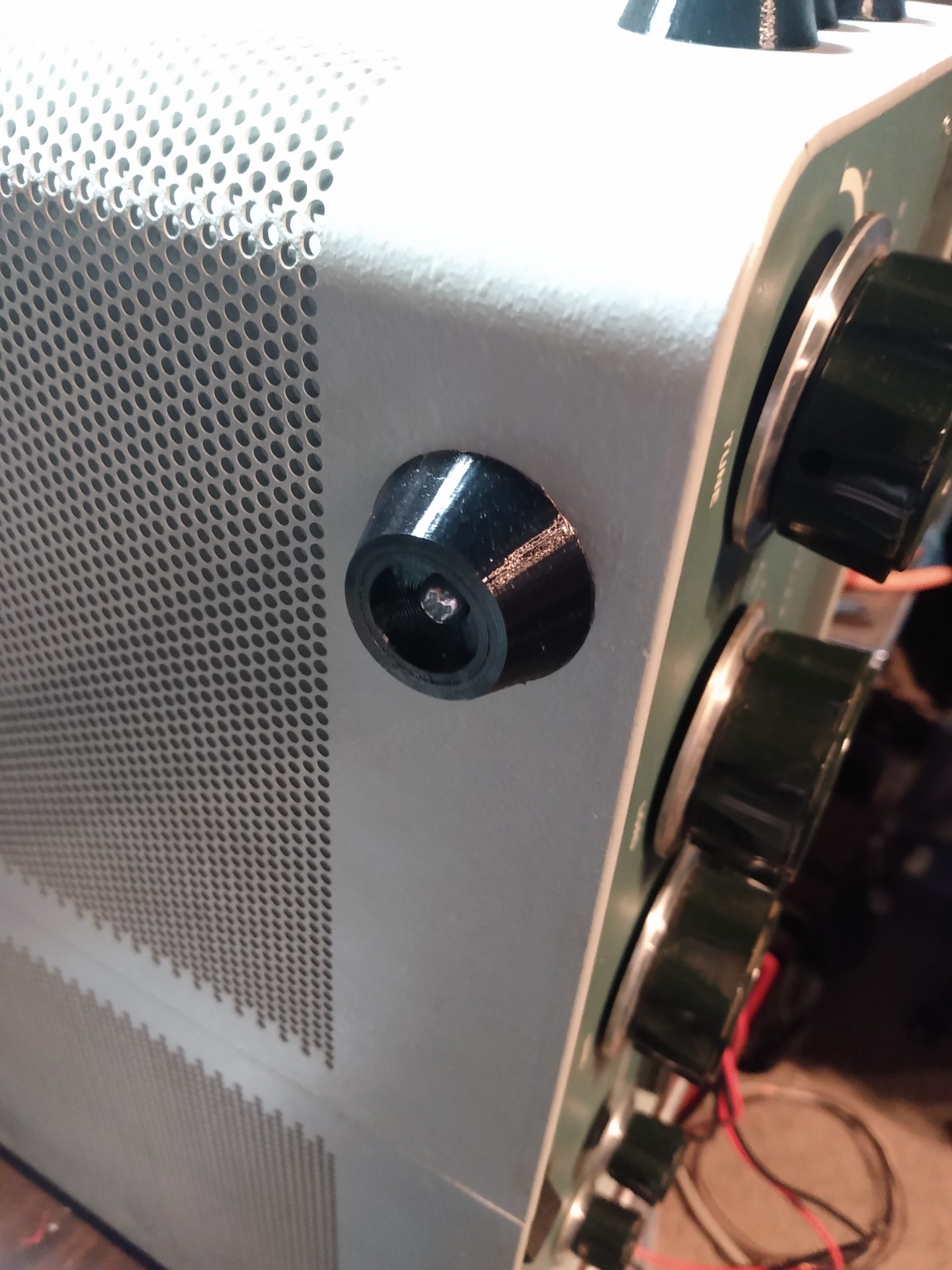
This is the end, right? Not quite. I noticed after screwing the feet into the bottom of the enclosure that the screws protruded below the feet and scratched the surface of my workbench. Also, these feet were a little high and I was concerned about the amp fitting into my radio rack with enough room for my tuner above it. So I decided to fire up the 3d printer again and give the SB-220 some new shoes. I printed 2cm high feet out of PETG that allowed the screw heads to recess into them. I also sourced 4 new screws from the hardware store that were 1/2″ shorter (cost: $0.04 USD), so the shorter feet would not cause the screws to protrude into the electrical components of the amplifier and cause an unexpected short. The amp sits like a lowrider, with just enough space below for adequate ventilation.

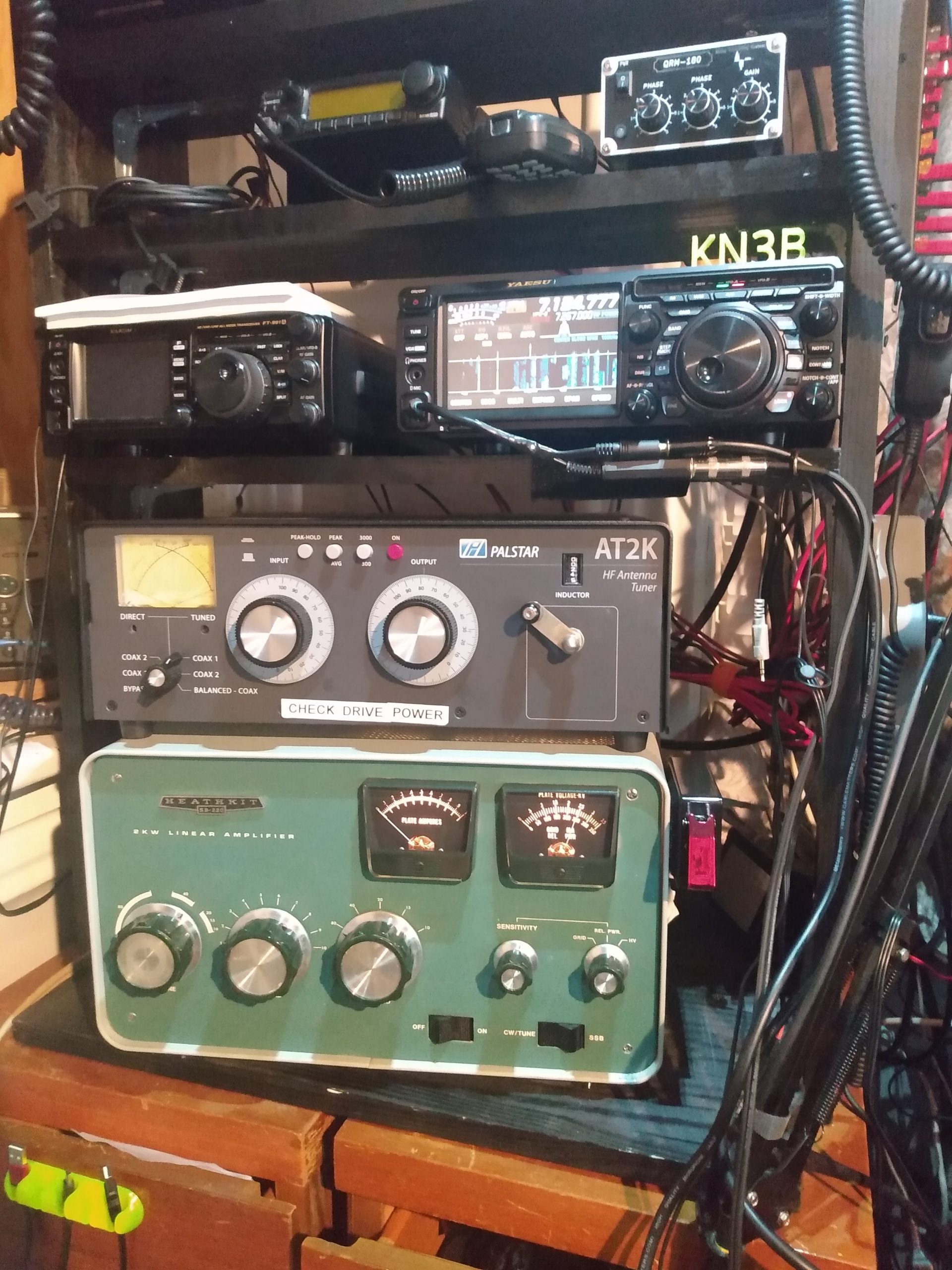
One modification that I wanted to do with this SB-220 was a standby switch. I operate a completely manually tuned shack, so there are times when I want to put 5w into an antenna to find a good tune, and that means having the amplifier out of the antenna system. Despite the 3-500ZG tube being “instant-on” and capable of being switched on and off repeatedly, I wanted to avoid the unnecessary stresses on the other components that come with these repeated power surges.
My original plan was to utilize the CW/SSB switch for an old-school standby switch and fan speed mod. A little history, condensed: This switch is a throwback to the days when the FCC required 1KW max input power on radio amplifiers for some reason (this was before my time so I’m murky on the details). These days this sort of thing isn’t required, and we are perfectly fine using the 2KW input that the SSB position on this switch provides. However, since I upgraded the keying circuit with the Harbach soft key mod, I wasn’t comfortable with the amount of modification I would have to do in order to get low voltage keying and the 120VDC of the fan circuit to coexist. I also could have added a toggle switch to the faceplate of the amplifier, but I wasn’t comfortable drilling new holes in what is a nice original faceplate.
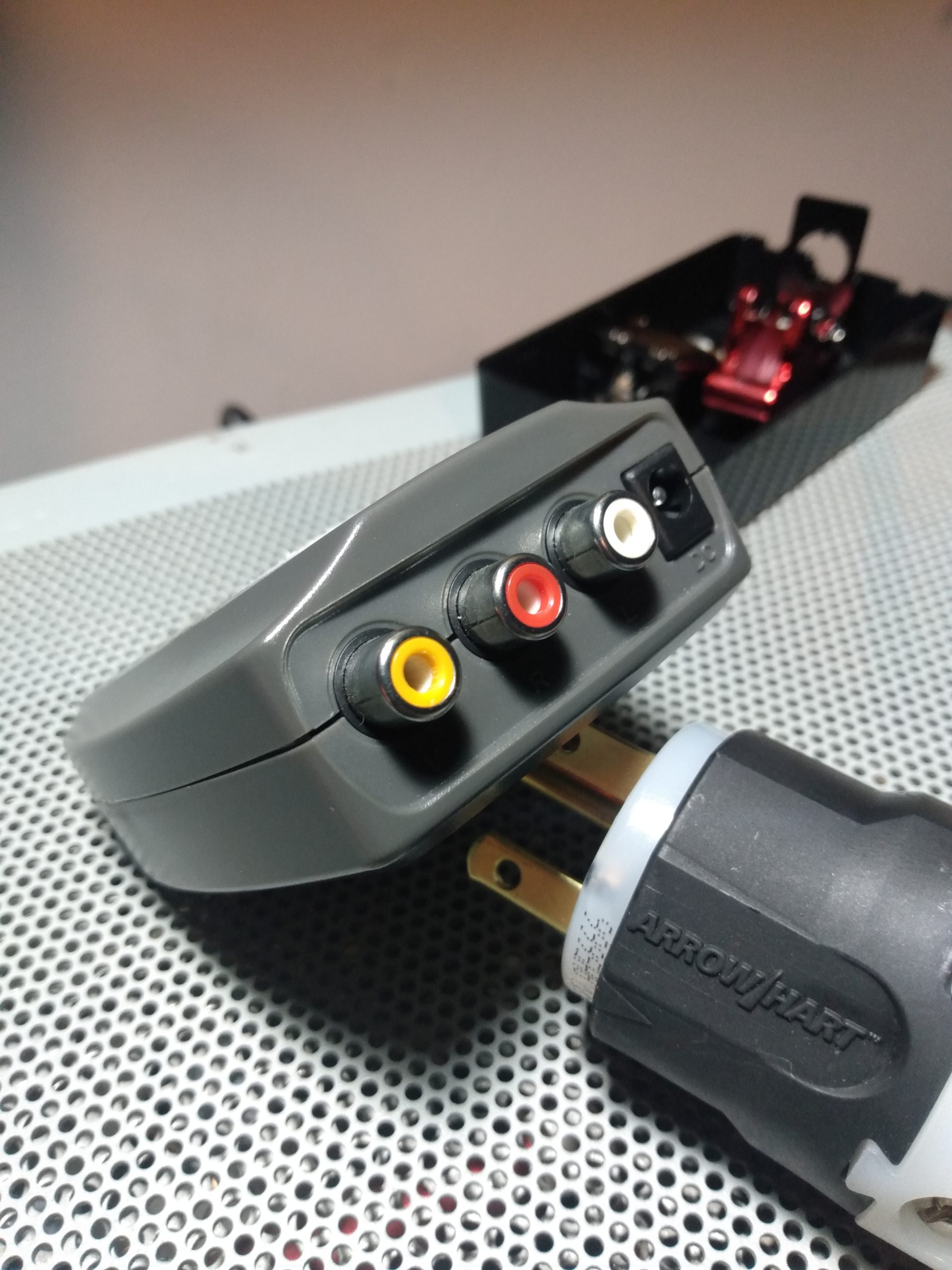
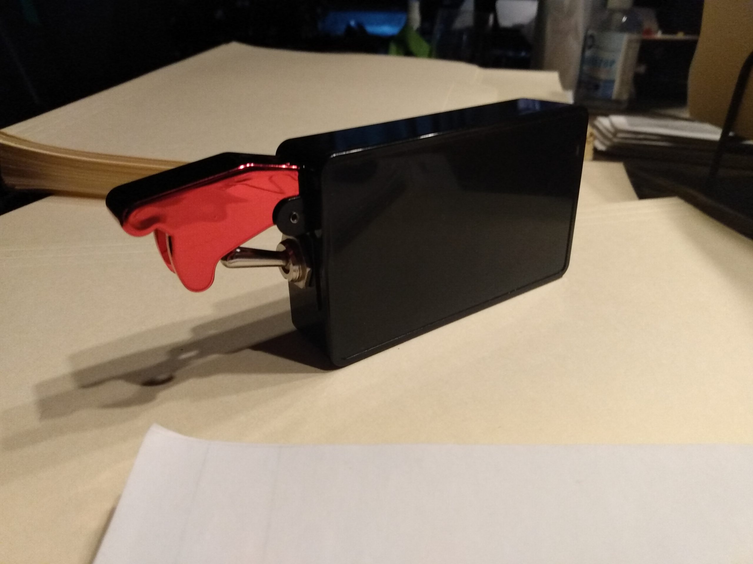
Instead, I would turn my keying cable into a standby switch. I wouldn’t get any fan speed modifications, but I would get standby operation. My original plan was to scavenge the required RCA connectors from an obsolete piece of consumer electronics, but the salvaged parts weren’t chassis mount connectors so I ended up scrapping that idea. Friend and neighbor Craig KC3MGN was nice enough to donate a pair of RCA chassis mount connectors to my project. I mounted these to a project box with a racing toggle switch, bonded the negative connections together, and ran the center conductor through the switch. With this box wired to the amplifier and the switch in the OFF position, keying up my radio would not key up the amplifier, leaving it in an on-but-standby state. With the red cover lifted and the switch in the ON (or GO BABY GO) position, the amplifier would key up as normal. I mounted the box to the side of the SB-220 with a strip of velcro, so there is no permanent defacement of the amp or enclosure.
The Heathkit SB-220 is still being tested, but it does put out a solid 1300+ watts on 40 and 80 meters, where it will be used the most. I have to do some antenna maintenance before I am comfortable attempting full power tests on the other bands, but early tests inspire confidence on 20, 15, and 10 meters.
Lessons Learned
This project took almost exactly 3 months to the day from picking up the amplifier to getting it on the air. After the cost of the amplifier, the Harbach kits, and several orders from Mouser, I believe I am in to the project for just under $1,000. I would do it all over again, if I were to find another SB-220 in the same or comparable condition.
Things I learned during this project:
Tube gear is resilient and can clearly take a lot of abuse. Even with the clear evidence of mistreatment and damage to some passive components, the rest of the amplifier was no worse for the wear.
Point-to-point wiring is so simple that you can work on it if you know how to flow solder. Don’t be intimidated by tube amplifiers, they are pretty simple and the schematics are easily digested if you know the basics.
Carefully inspect each and every circuit in your amplifier before you order parts from Mouser, otherwise you’ll spend about $35 in extra shipping charges because you had to order two capacitors five separate times over the course of the restoration.
And finally, if you find an old beat up tube amplifier for a good price, take it home and restore it before somebody else does.
I read the whole thing tonight. As proof, I found the word “deformed” where, I believe, you meant “reformed.”
This is brilliant work. Brilliant applies to both the overhaul, and the documentation I just read. Carry on, Mr. QRO.
Bueno restomod. FB putting all the parts back together again. I also respect the attempts to keep the spirit of the original intact.
73,
KC3MGN
Hello!
I read with great interest your restoration of the Heathkit SB-220.
I recently acquired an SB-220, and I will be performing many of the same improvements and modifications that you had performed.
I was paying attention to your comment about the 150 ohm glitch resistor you had installed. That value appears to me to be way too high, with a close to 100 volt drop in the B+, and a power dissipation of way over this resistor’s rating of 25 watts.
Is this value you had installed possibly an error? And you had indicated that you had miswired the glitch resistor. Could you clarify this for me? I believe it should be located at the output of the B+ filter capacitor bank, and just before the L2 VHF choke.
With regard to the parasitic suppressors in the plate leads; the previous owner had installed two different lengths of nichrome 60 wire between the RF plate choke and the DC blocking capacitor. This was a very well known modification designed by the late Rick Measures, to be used in conjunction with the parasitic suppressors that were previously installed within this amplifier. I noticed that you had removed the two lengths of the nichrome 60 wire; did you possibly replace them, to work in conjunction with the parasitic suppressors, which were also a Rick Measures design?
Thanks very much in advance for your time and guidance!
73,
Bruce, W2XR
I am rebuilding an SB-220 that I bought from an old ham who had stored the amplifier in his garage (literally) for about the past 4 – 5 years, I stripped and disassembled it completely and washed the chassis thoroughly and am now, almost finished rebuilding it. But I have some questions.
Question 1 is: Would it be wise to protect the HV transformer by fusing the secondary prior to the power supply board and power supply capacitors? If so, any idea where and how this would be accomplished? What size fuses with be appropriate?
Question 2: This question surrounds the rebuild of parasitic suppressors. Is whether the wire I have used (#14 solid copper) the best wire to use. I have new, old stock Heath parts that I can use on both tubes, but I know I can do better than the OEM parts and more effectively protect the tubes. I have used #14 solid copper wire along with two 100 ohm x 2 resistors. on each tube’s suppressor. Otherwise I have followed you design.
Last question: The strap which runs from the DC blocking capacitor mounted on the back plate of the tuning capacitor, to the parasitic suppressors is nothing more than copper braid filled with solder. This was in the assembly manual this way. This seems inadequate to me. Would using a solid copper strap in place of the soldered copper braid be more effective?
I appreciate very much you sharing your experience with the rest of us.
Hello Dave,
1. I’ve never seen this done as a modification and I don’t think it would be necessary.
2. There is much debate about parasitic suppressors and the wire type used here (copper vs nichrome). I did go with solid copper and have been told this is sufficient. Some say that nichrome is preferred, I’ll test this eventually. I haven’t had any problems so far. For what it’s worth, I’ve also heard from several people smarter than me that the original Heathkit designs were just fine and all the modern designs are unnecessary!
3. Solid copper strap vs. copper braid shouldn’t make much difference. I’m currently using the same copper wire I used to build my parasitic suppressors. I have also seen nichrome bent into weird shapes to help with preventing parasitic oscillation, again I don’t know how effective this is.
Hi Brad… thank you for taking the time to document this work. I’m tearing apart an SB-220 that several hams must have had their hands into. It has several modifications with no documentation so I’m painstakingly reverse engineering it so I can document it. Mine also had a semi-kludged power cable setup. I’ve had to take that whole assembly out and re-do it. Trying to find a suitable grommet has been quite the challenge since the previous owner only used black electricians tape and tie-wraps. It’s a slow process but I’m enjoying it. Having the photos and the documentation you have done has helped me understand some of the design by Heathkit as well as the improvements you and Harbach made. I’ll hopefully have this back on the air by summer! Thanks again.
Estupendo artículo para los poseedores de estos antiguos y estupendos amplificadores.
Felicitaciones !
Great article, I have no input and would like to say enjoyed each comment submitted
I got a sb220 wired for 240 and I can only get 500 watts on 20 meters, the other band I get 900 plus.