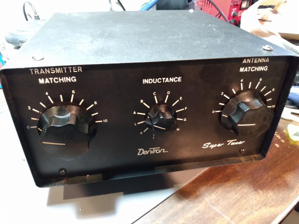
A few months ago I bought a 1KW Dentron Super Tuner antenna tuner from a friend. I didn’t really have a need for it, and these tuners lack modern conveniences like roller inductors and meters, but they are well reviewed and regarded as very capable for QRO under 1000 watts. I planned on bundling it with an amplifier at a hamfest, but it sold online before that could happen. I have no problem with this, because I’m perpetually out of room to store unused gear, and less gear cluttering my shack is a Good Thing.
Actual footage
I had a busy Monday, and lots of packages to drop off at the post office. As I hefted a large box of First Class Mail packages onto my shoulder, the box containing the tuner tumbled out of the backseat of the truck and hit the pavement with a BONK that could only be interpreted as catastrophic. I figured out how to transmute an antenna tuner into maracas.
I sell a lot of stuff on the internet, and as the sales director of American Light and Fixture’s shower curtain ring division, it’s my job to make sure customers are happy or I don’t get paid. I have the same philosophy when it comes to selling ham gear. So my #1 ham radio priority was to fix this.
I contacted the buyer and explained the situation, and they were fine with the tuner being repaired, as long as it worked. It turns out that dropping the tuner outside the post office may have been a blessing in disguise.
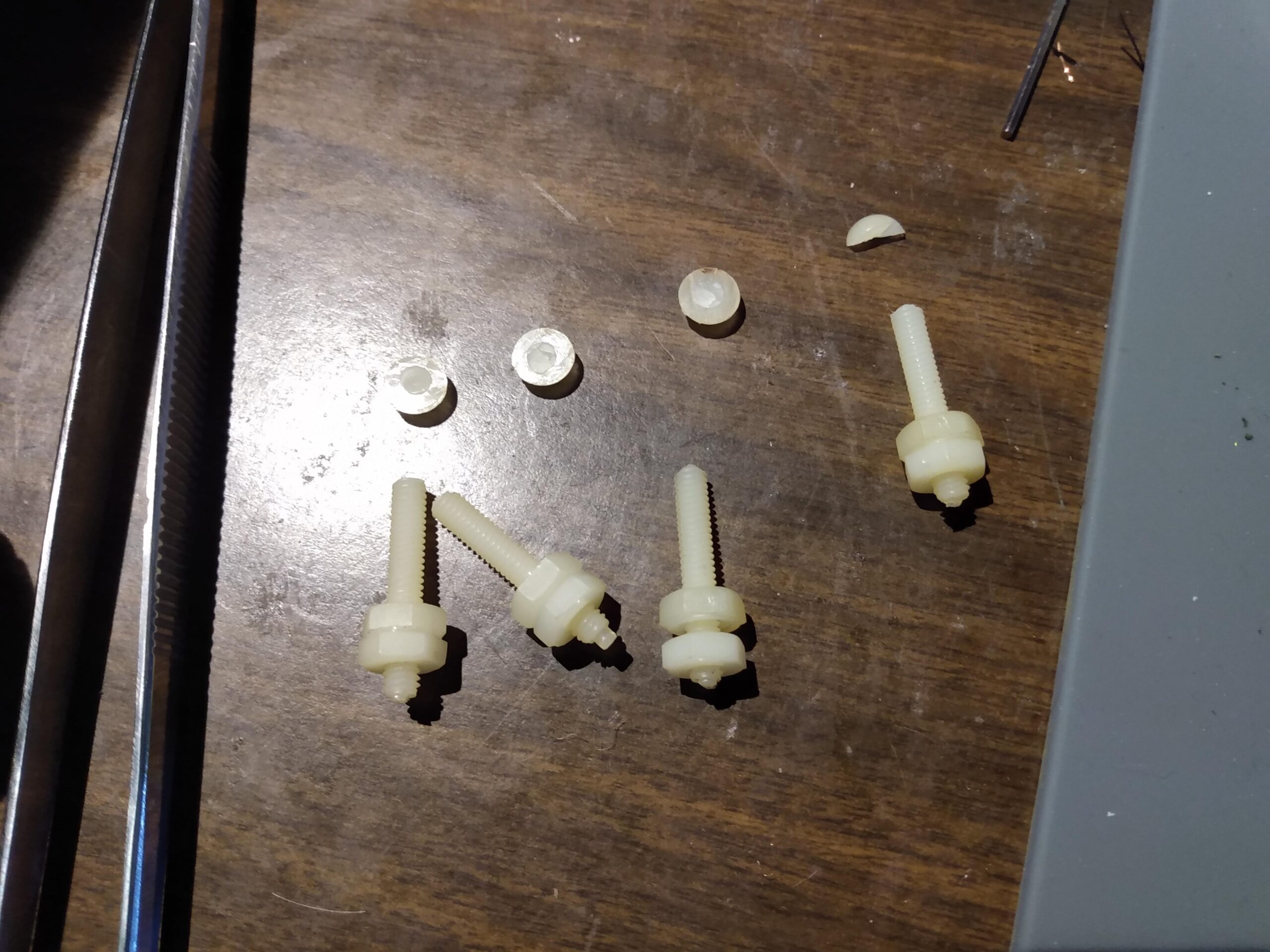
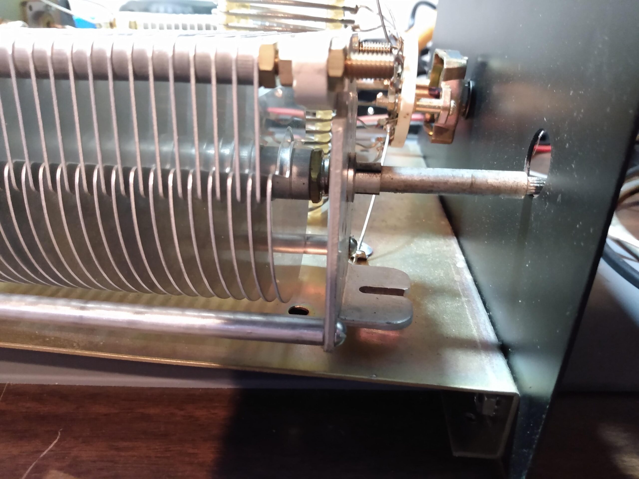
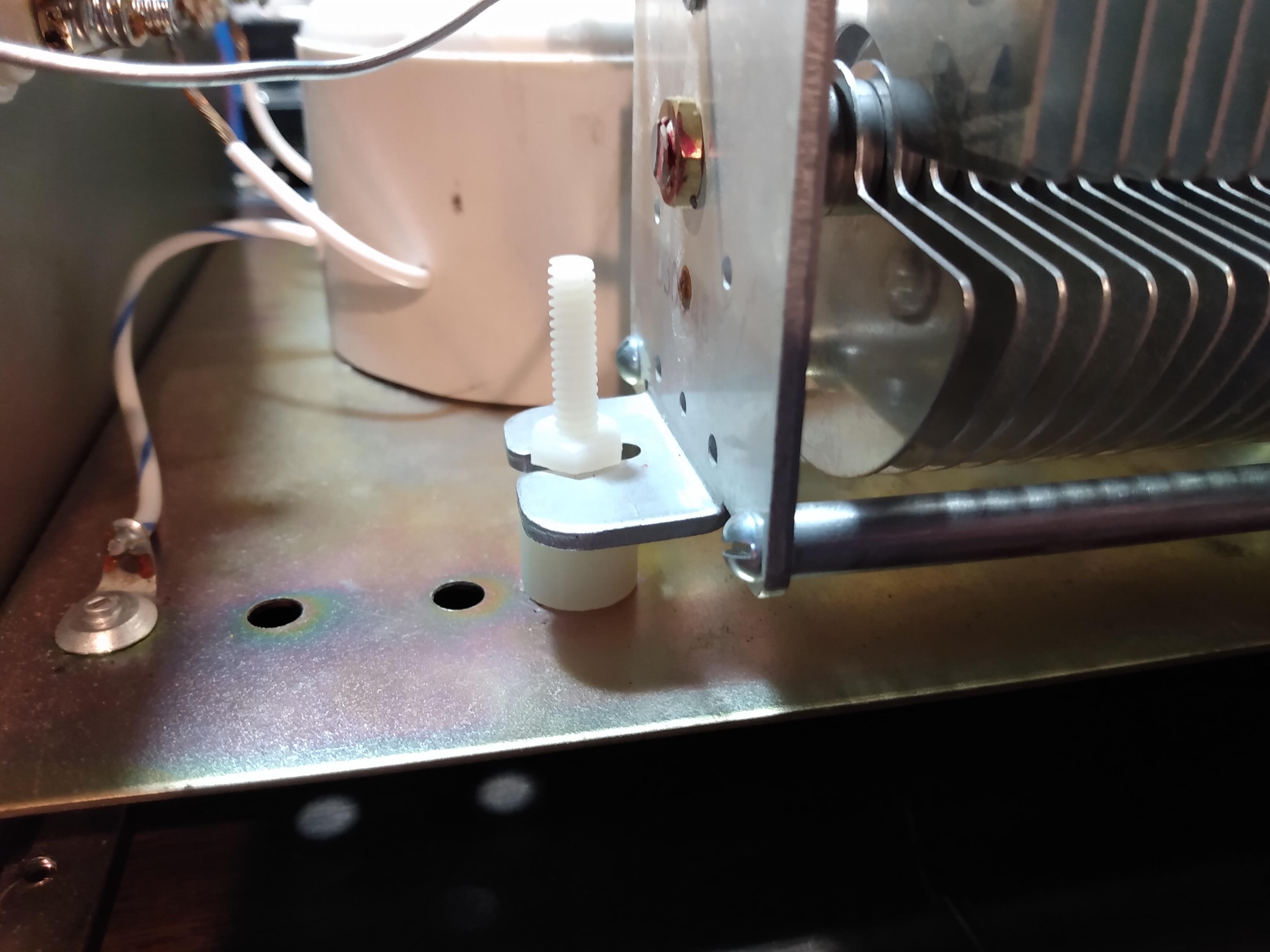
Electrically, the tuner was fine. But the two air capacitors inside the Dentron Super Tuner are isolated from the chassis ground by two pairs of nylon spacers and nuts/bolts. These bolts are what snapped when the tuner fell, and some light research concluded that this is a pretty common problem when shipping these Dentron tuners. The tuner was at least 40 years old, and the bolts were dry and brittle. Not surprising.
My first thought was to replace the mounting hardware with steel nuts and bolts, but my lizard brain said “there’s probably a reason they aren’t conductive,” and instinct was correct. The schematic for the Dentron Super Tuner shows that the air capacitors are not grounded to the chassis, because doing so would cause a short in the antenna system. I had to isolate them from the chassis or the tuner was useless.
The first hardware store I visited was pretty well-stocked, but apparently nobody knew that nylon hardware existed. The second was better stocked and had replacement parts that would work. I replaced those original dried and brittle nylon 8×32 nuts and bolts with slightly thicker 10×24 nylon parts. It was a tighter fit, but the thicker hardware decreased the possibility that these components would break under typical shipping stresses.
Capacitor rearCapacitor frontElectrical tape is like duct tape for electronics
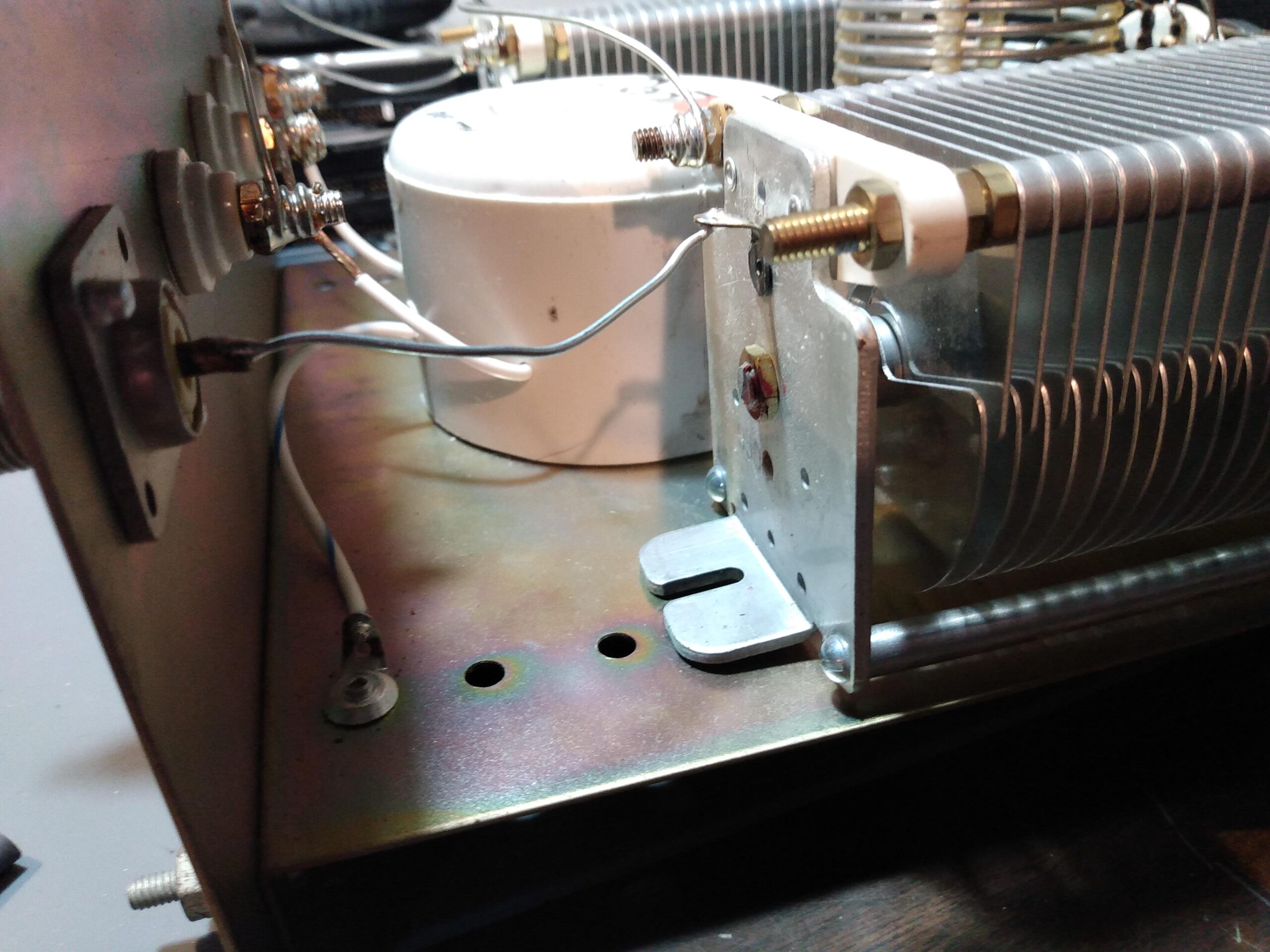
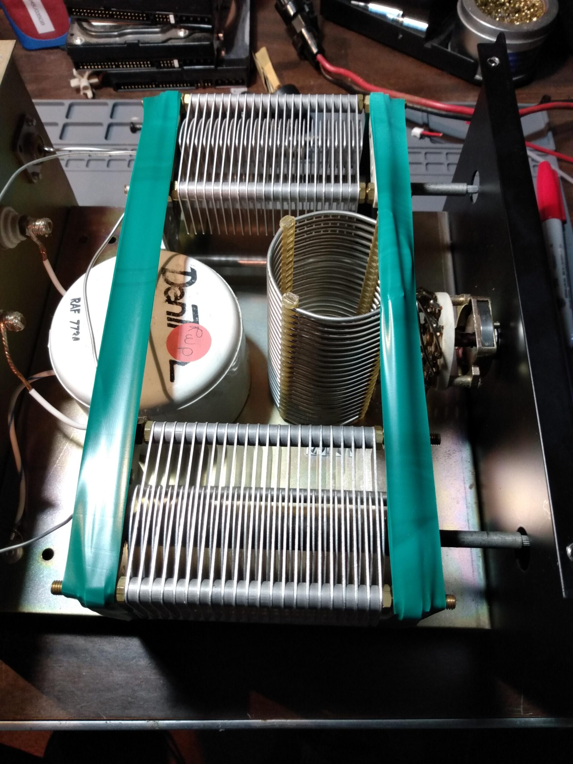
I couldn’t guarantee that the new parts wouldn’t break in transit, so I wrapped several courses of electrical tape around the air capacitors at each end to hold them to the chassis in case the bolts break again. I didn’t really expect the electrical tape to do much of of anything in the event of trauma, but anything that might keep them from bouncing around inside the chassis seemed helpful. I made sure to wrap the electrical tape so it does not interfere with the blades of the capacitors, so the buyer could leave it in place if they preferred.
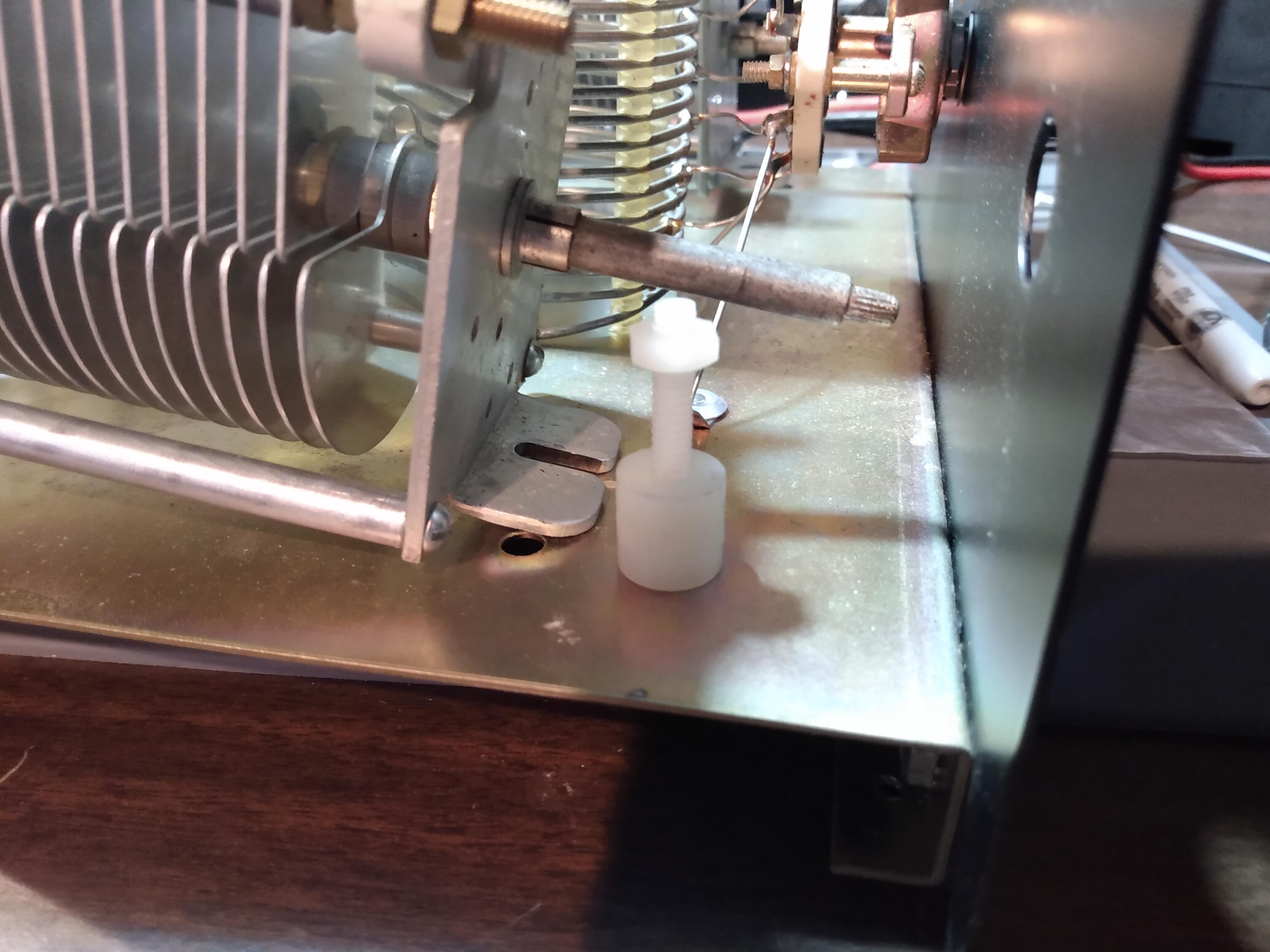
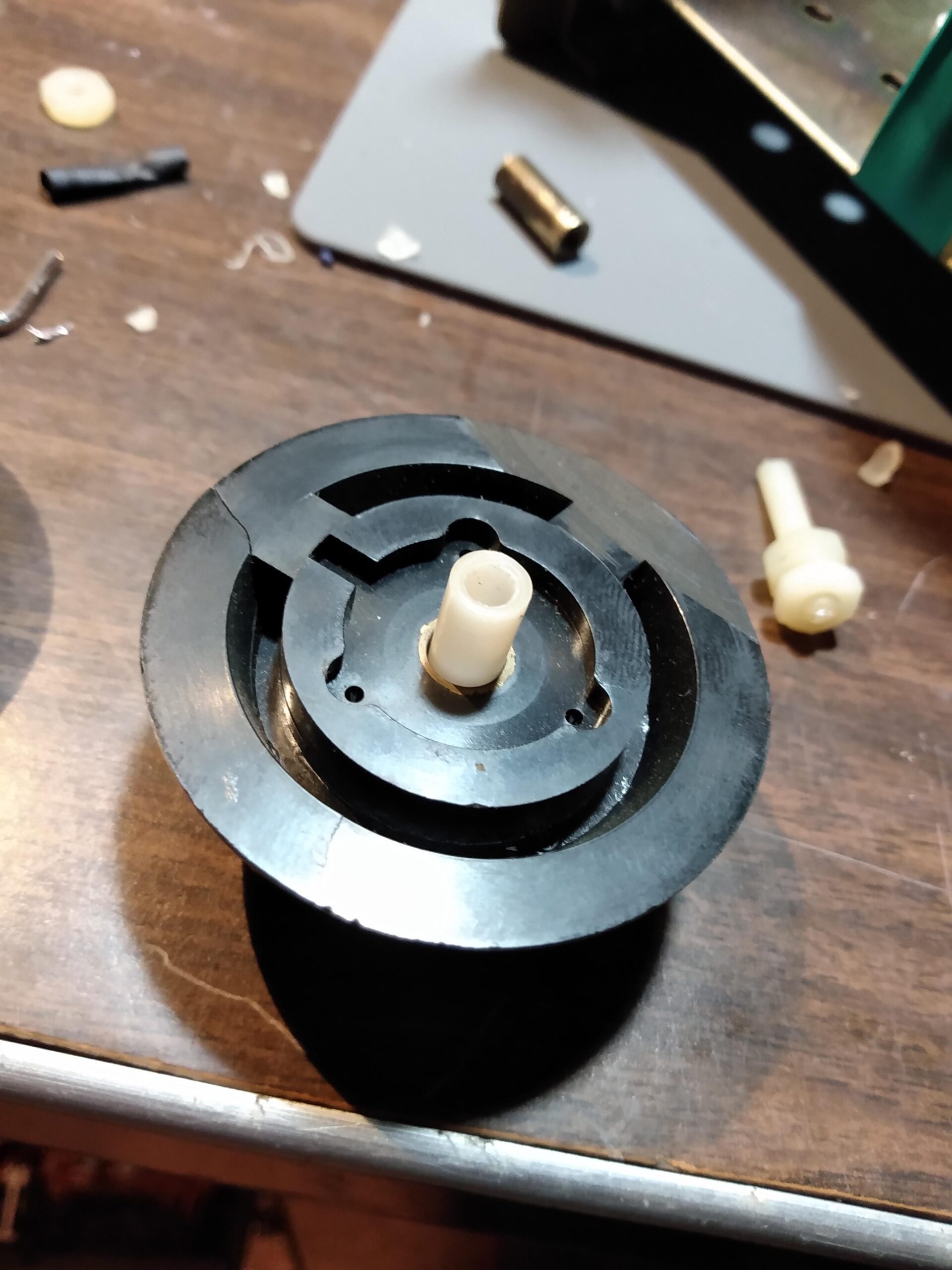
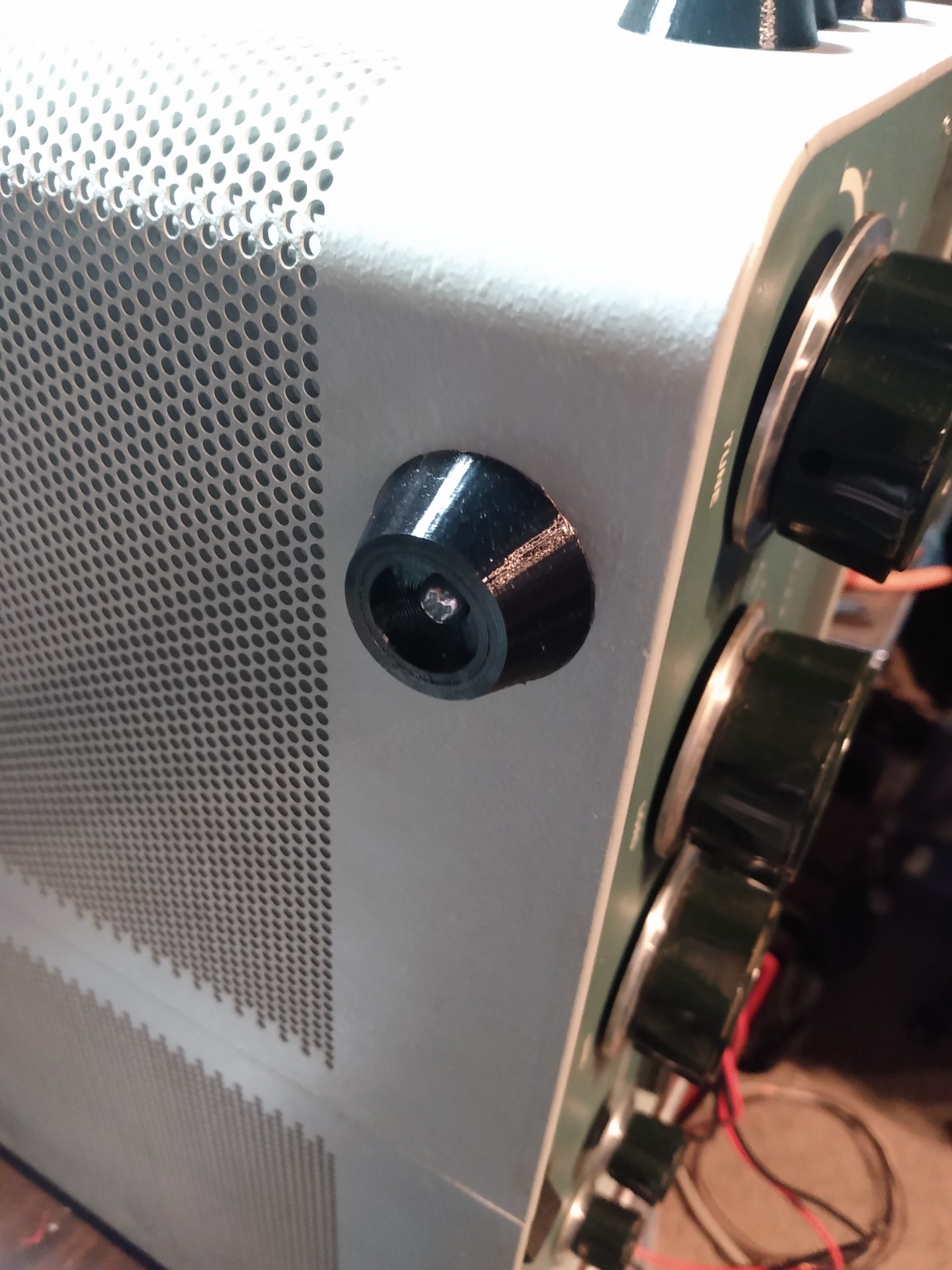
The other problem I uncovered was with one of the connections between the knob and the shaft of one of the air capacitors. The knobs for ANTENNA matching and TRANSMITTER matching are connected to the shafts of the variable capacitors with a 1/4″ nylon dowel drilled to press-fit onto the capacitor shaft, which is then held by the knob via a worm screw. Only one of these was present. The other knob was held in place with a 1/4″ brass fitting which was cross-threaded onto the shaft of the capacitor (poorly). If the tuner hadn’t been dropped, I wouldn’t have noticed this, but I suspect it would have come loose in transit.
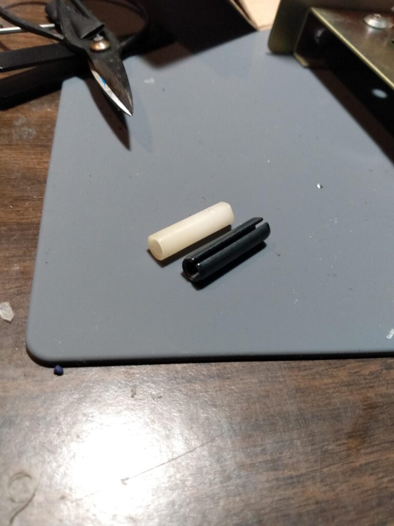
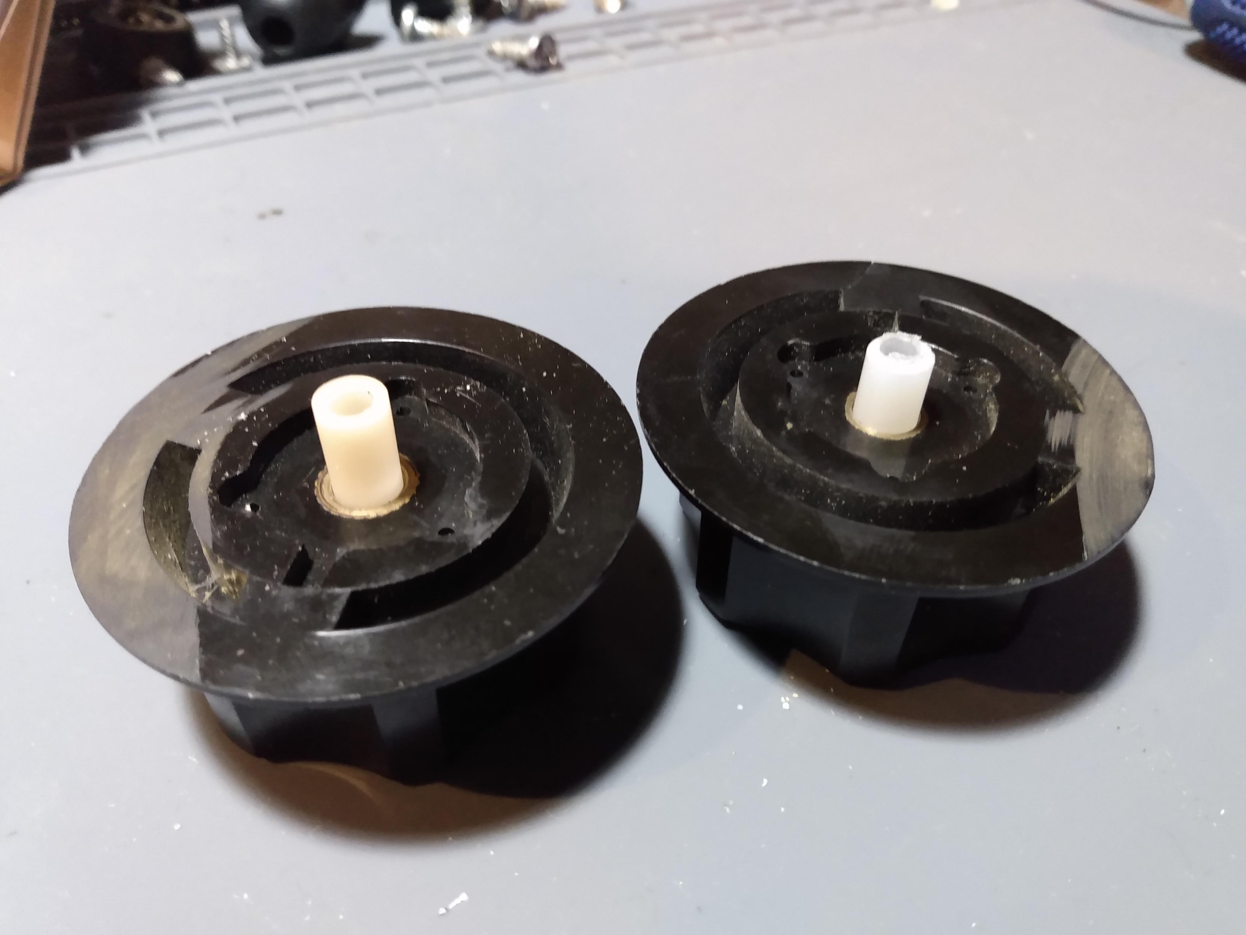
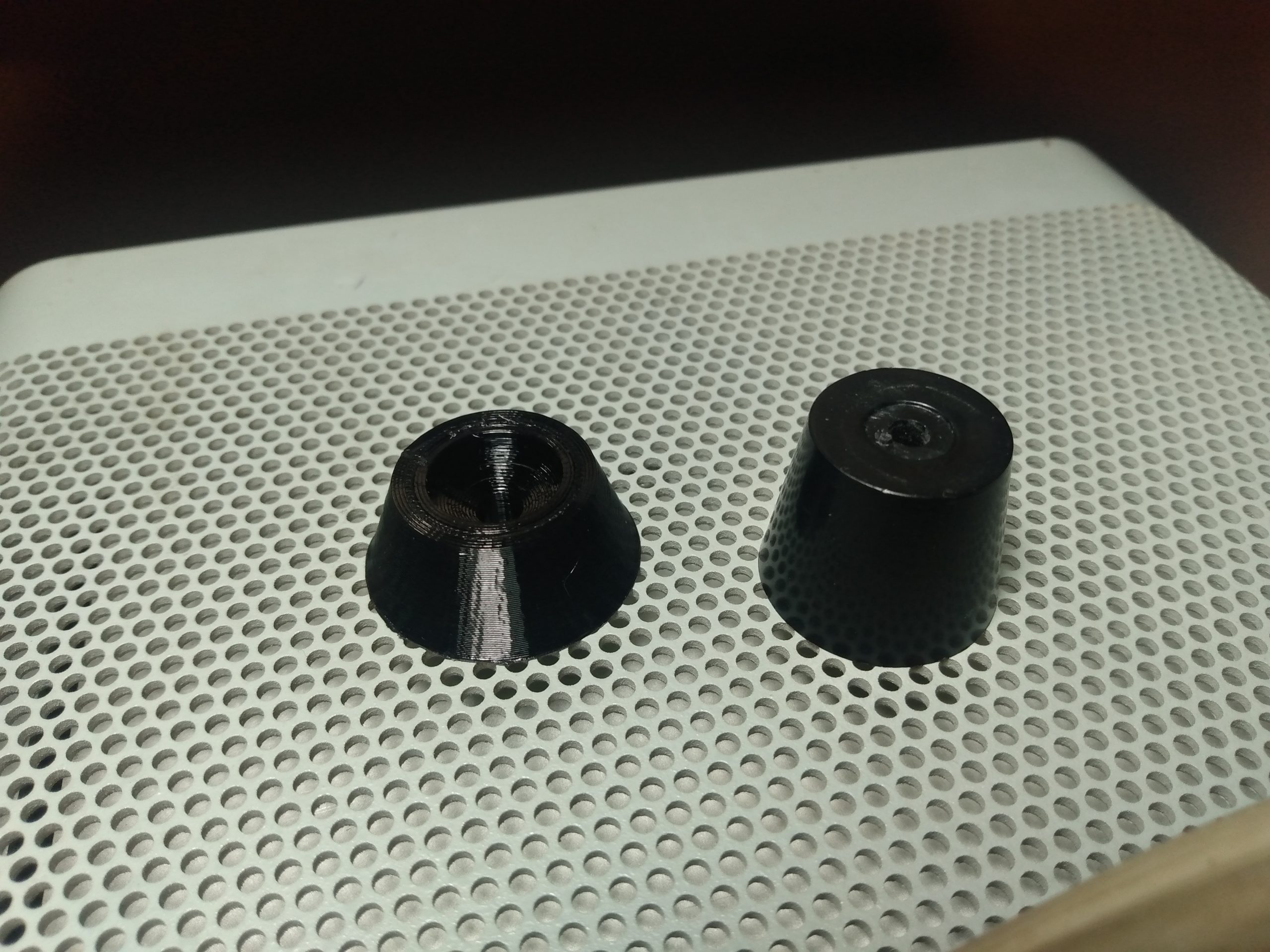
Nylon nuts and bolts are hard enough to source, but 1/4″ nylon dowel is almost impossible to find in the hardware stores of Small Town, USA. I found a 1/4″ x 1″ steel roll pin that I attempted to use as a replacement, but it didn’t quite work. Luckily, friend and neighbor KC3MGN pulled some strings and was able to source a short piece of 1/4″ nylon dowel, which I then cut to length and drilled on one end to press fit onto the shaft of the capacitor. The result wasn’t visually perfect, but I challenge anybody using the tuner to tell the difference.
Nylon vs steel roll pinFactory nylon adapterFactory nylon on left, DIY on rightUgly, but fully functional tuner
This project raised my blood pressure. But The Dentron Super Tuner is a better tuner after the damage than it was before, just because it brought these issues to my attention. If not for my butterfingers, it probably would have arrived damaged anyway. I suppose some things happen for a reason, and I hope the buyer gets a lot of use out of this tuner for many years to come.
I made the trip to the York Hamfest on April 29 along with N3ZIO and KC3UYG, despite a dreary weather forecast and a 2.5 hour drive. There was lots of rain, temperatures in the 40s, and a completely saturated grass field. It took under a minute to completely soak our shoes, and by the end of the morning the trampled mud in the tailgating area rivaled that of Woodstock ’94.
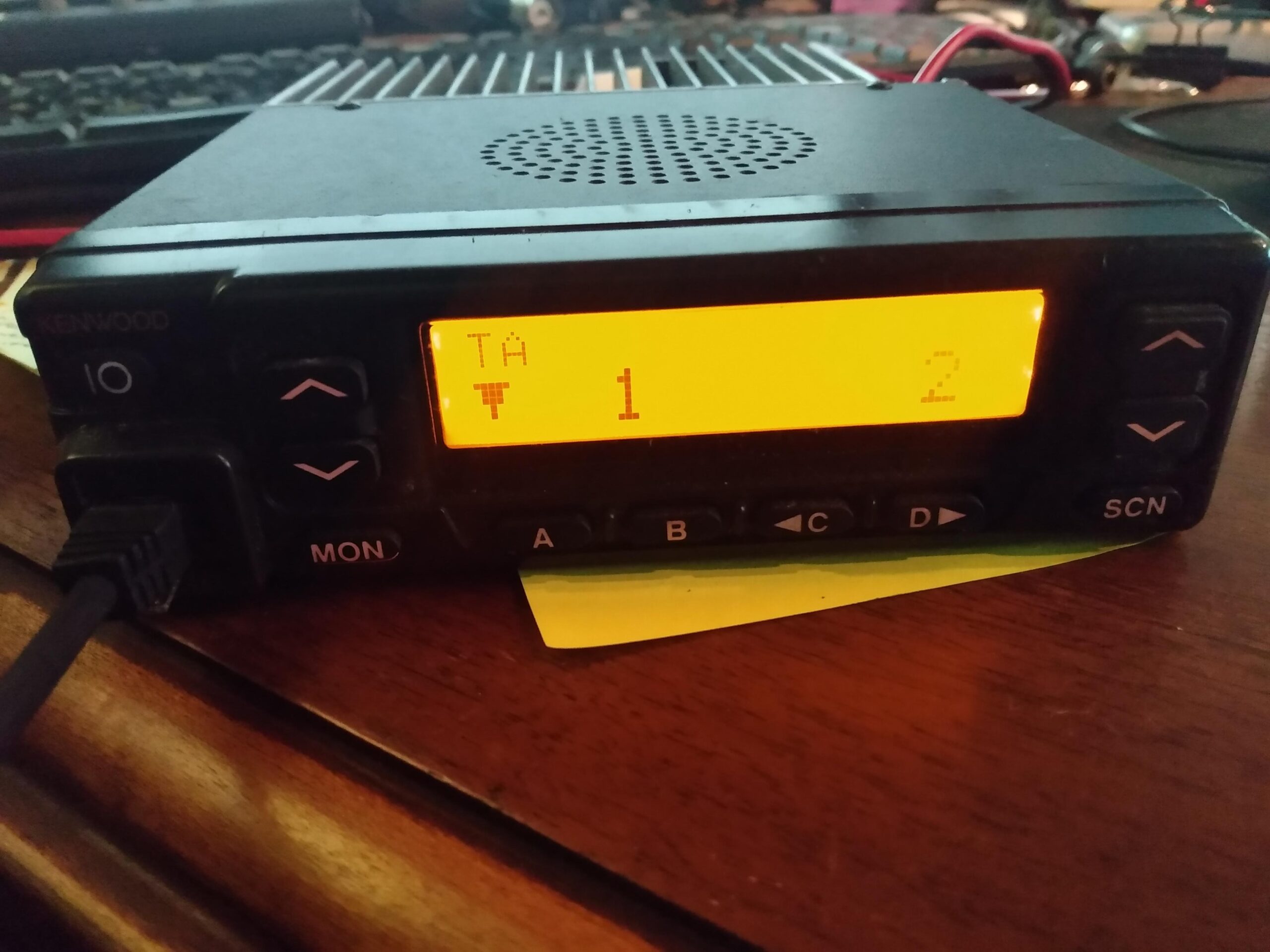
But despite the weather and slightly diminished attendance, there were some deals buried among the totes of miscellaneous parts and rusted old gear. One of these deals was the pair of Kenwood TK-780 VHF radios I found for $2 each. Not knowing if they worked properly or even powered on, I purchased them. I may never financially recover from this…
The form factor of the TK-780 is familiar to me because I have some experience with the TK-981, which is a 900MHZ FM commercial radio that is commonly repurposed for ham bands. The TK-780 is a commercial radio an identical form factor and button layout to the TK-981, but with VHF capabilities, so I bet on the programming procedure being more or less the same.
Upon my return home in the mid-afternoon, I located my Kenwood power cable and tested the first TK-780 for power. All systems normal! The second TK-780 had Powerpole connectors instead of a Kenwood power adapter, which was fine with me, and it was in this moment that I realized that I always had the option to do this to my radios, but it never occurred to me to do so. The second unit also powered on, so on to the next step.
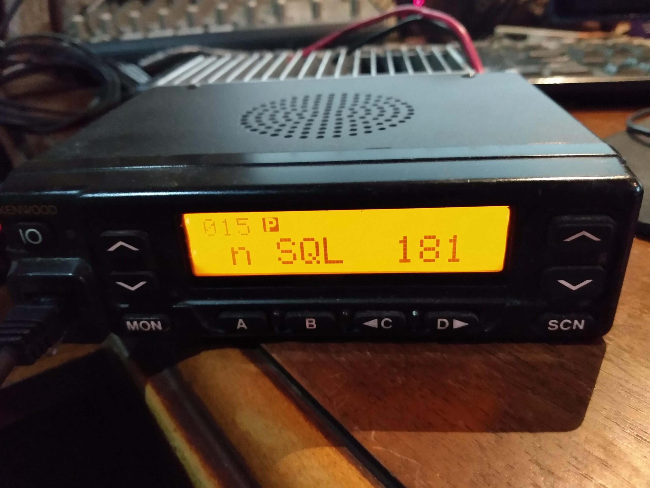
Powered on with default programming
A common question asked when repurposing the Kenwood TK series of radios is: Can they be programmed with Chrip? Unfortunately, that would be too easy and the answer is no. There are a handful of applications released by Kenwood that can be used to program their commercial radios, and the specific application you would use depends on your model of radio. I did a few minutes of minimal research and found that the TK-780 could be programmed with the KPG-49D software that I used for the TK-981, and it utilized the same Kenwood KM6 programming cable. Thank Hiram Percy Maxim for smiling upon me.
Something to keep in mind when dealing with these radios is that they are commercial radios first and foremost, with the capability to be repurposed for amateur radio use. As such, they have certain quirks and will lack some features you’d otherwise expect out of an amateur radio. In addition to this, it’s expected that these radios are configured and programmed for use in commercial applications, and the software used to program them assumes you’re doing so.
That being said, I like how the KPG-49D software works with these radios. I’m told it’s not possible to brick a Kenwood TK radio, which is reassuring. And I was able to read the configurations from each radio without even specifying what model it was, because the KPG-49D software detects it automatically. The downloaded configurations confirmed to me that the TK-780 was virtually identical to the TK-981. I saved the known good configuration and channel list, and set out to make a new config that I could test on my local repeater.
When trying to write a config to the radio that contains frequencies in the 2m ham band, I was getting a warning that some frequencies were outside of the capabilities of the radio. Under the Model menu, I was given an option for frequency ranges of 146-174 MHz or 136-162 MHz. This warning did not appear during programming with the frequency range set to 136-162 MHz. I do not know if this changes anything within the radio itself, it just stopped the error from appearing during programming.
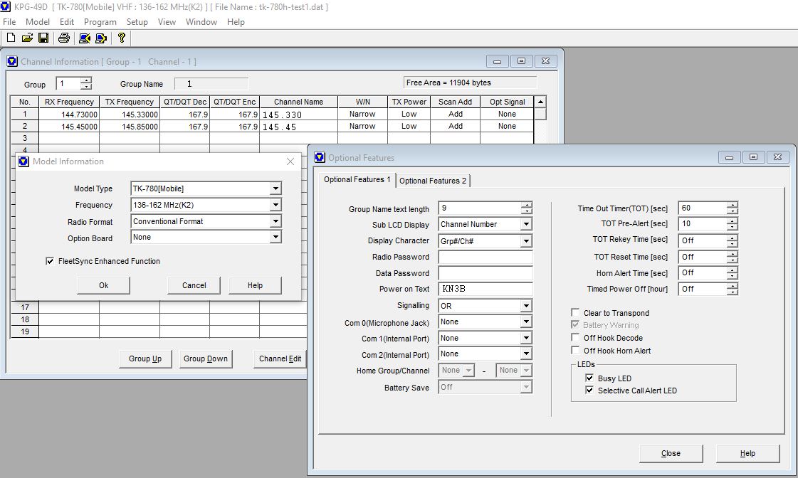
The bulk of the configurable options for 2 meter amateur use are going to be found in the Edit menu under the Channel Information, Optional Features, and Key Assignment menus.
Channels, optional features, and model information
Channel Information is easy enough to figure out, it very closely represents the channel list you’d see in Chrip: RX/TX frequencies, Decode/Encode tone squelch, Channel Name, Wide/Narrow FM, and TX Power. I encountered a head-scratcher with the Channel Name setting, which leads me to the Optional Features menu.
In the Optional Features menu under the Optional Features 1 tab, there is a field for Group Name text length. Setting this to anything other than None caused my radios to not show the channel name at all, and instead simply display zone and channel numbers. Not sure why this is the case, but setting it to None and setting Display Character to Channel Name caused my channel names to display correctly. I also set my Sub LCD Display to Channel Number, because knowing which numerical channel you were on seemed to make sense to me. The only other option on this menu that I felt the need to change was the Power on Text, which I set to my callsign, because I could.
The Key Assignment menu allows some minor UI changes to be made in the form of button function reassignment, but some of these options may not be permitted depending on the firmware version of the radio. I was unable to set the Home Channel option on mine without a critical error. I haven’t made many other changes here yet, since the basic functions of monitor/volume/channel selection are already enabled by default.
Before the configuration can be written to the radio, the COM port has to be set via the Setup > Communication Port menu. The KPG-49D software is unlike a lot of other radio programming software in that it does not need to be restarted if you forgot to plug the cable in first. Simply plug in cable, wait a few seconds, and select the newly enabled COM Port.
Time to program the radio via Program > Write Data to Radio. It doesn’t take more than a few seconds, and the radio reboots afterward. Normally this would be the last step and you’d be free to use your radio, except I ran into a problem that stumped me for about an hour.
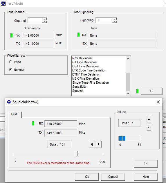
With an antenna connected, it seemed to be receiving static constantly. It would also receive my repeater traffic whenever I keyed up from another radio, which is normal, but then it would just go back to receiving static after the repeater transmission ended (most of the time, but not every time). I was using a temporary magmount antenna on my office whiteboard, so I expect it was receiving a ton of RF interference from something nearby. I tried to find a squelch option, but there was no squelch option to be found, either via the buttons on the radio or via the Optional Features menu!
There is actually a reason for this. In an FM commercial radio setting, there are very few instances where an employee or emergency responder would be required to modify squelch settings, so this isn’t an option either via a radio menu or front panel button. This led me to Test Mode under the Program menu. In the KPG-49D software, Test Mode allows us to make a live direct connection to the radio to change system options, one of which is squelch level. I adjusted it high enough that it would break for repeater traffic, but not for RFI and the problem seems to be solved.
TK-780 Test ModeRadio in test mode
You might ask, “I thought you had TX/RX tones set, why wouldn’t that keep the radio squelch from tripping due to RFI?” The answer is: I don’t know, this is just how I fixed the problem.
As is tradition with my radio projects, solving one problem just means there’s another problem to deal with, and in this case it was during transmit. I could receive repeater traffic just fine, quite well in fact. However, when I tried to transmit to my local repeater via the TK-780, I could key the repeater but no audio was transmitted with any of the Kenwood KMC-27A microphones that worked with my TK-981. Different mic pinout maybe? I didn’t want to get that into it, and opted instead to order a newer 8 pin Kenwood KMC-32 DTMF microphone for $17 and hope for the best.
I made the right choice. As soon as the mic arrived I plugged it in and made a QSO on the KB3DXU 145.330 repeater with KC3AHR. I received a good audio report and no complaints about signal on either of the two radios set to low power.
I guess the moral of this story is to buy $2 commercial radios if you already have the programming cable and software. Even if you have to make those investments, a used TK-780 is a perfectly acceptable option when you consider the fact that a new amateur VHF mobile radio from one of the Big 3 amateur radio manufacturers is still well over $100.
Living on the floor of a valley in the Appalachian Mountains doesn’t make for very good day-to-day weak signal VHF operating. Normally I don’t bother doing 2 meter operation unless it’s talking to one of the nearby mountaintop repeaters. But the January and June VHF contests are the exception, and I take these opportunities to set up portable operation on a nearby ridge.
The contest didn’t start until 2PM local time, so I eased into my morning by drinking some coffee, working on some QBM, and working some 10 meter sideband DX before the North American QSO Party started.
I arrived at my operating location, the intersection of PA Route 554 and Skyline Drive, at precisely 1PM. I chose this location not because it is the best ridge to operate VHF from (I’m sure it’s not), but because it is only about 4 miles as the crow flies from my home station, is in the same grid square (FN11), and is about 1500 feet in elevation compared to 500 feet of elevation at my QTH on the valley floor.
Conditions were approximately 32 degrees and overcast, typical January weather in Pennsylvania. The area I operated from serves as a parking area for people utilizing the nearby hiking trails, so there were several cars taking up space. Luckily the owners of these cars emerged from the woods just as I was trying to figure out where to park, so I secured an ideal spot.
In the June 2022 VHF contest I had beams for 2 meters and 6 meters. My 6 meter beam isn’t really meant to be repeatedly broken down and transported, so I decided to stick to 2 meters for this trip. I was doing this portable operation alone and it would simplify setup and tear down.
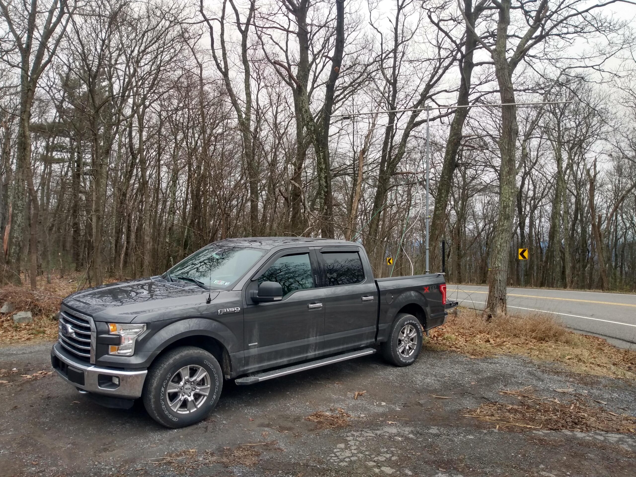
Unwashed vehicle with mast and beam
The antenna I use for 2 meters is an older Cushcraft 13B2 yagi that was generously given to me by Dale N3ZIO. When I received it, it was missing a couple elements, but MFJ was able to get them to me (eventually) for a few dollars each. It has 13 elements and provides 15.8 dBi of gain, a 26dB front-to-back ratio, and is about 15 feet long. It breaks down into 3 pieces for transport, which is just about perfect for fitting into the bed of my truck.
Cushcraft 13el 2m beam
The mast the beam is mounted to is nothing more than a Harbor Freight telescoping flag pole with hose clamps to lock the sections in place. It’s not an elegant piece of hardware, but it was affordable and easily holds the weight of the beam. I should also mention that this particular mast’s bottom two sections are kind of stuck together, so actual height is only about 17 feet. This is fine for 2 meter work, since it puts the beam more than 2 full wavelengths above the ground. The plastic hooks on the mast (where a flag would normally attach) are excellent mounting points for guy lines, because they allow the mast to rotate, which means the beam can rotate as well.
The mast is held upright by a trailer hitch mast mount. The mount is long enough for the tailgate to be lowered with the mast in place, which makes mounting the beam to the mast very easy. I mounted the center section of the beam with the mast in its lowered position, attached the front and rear using a single stove bolt for each, connected the LMR400 coax to the antenna, and began raising the beam.
As I raised the beam, I also guyed it using paracord to two cleats at the front of the truck bed, and a tree directly behind the truck. I used some high visibility 3D printed paracord hooks to keep the lines tight. Surprisingly, there was no wind at this operating position so I would not have to stress test the limits of the paracord hooks. Perhaps another time.
Operating position
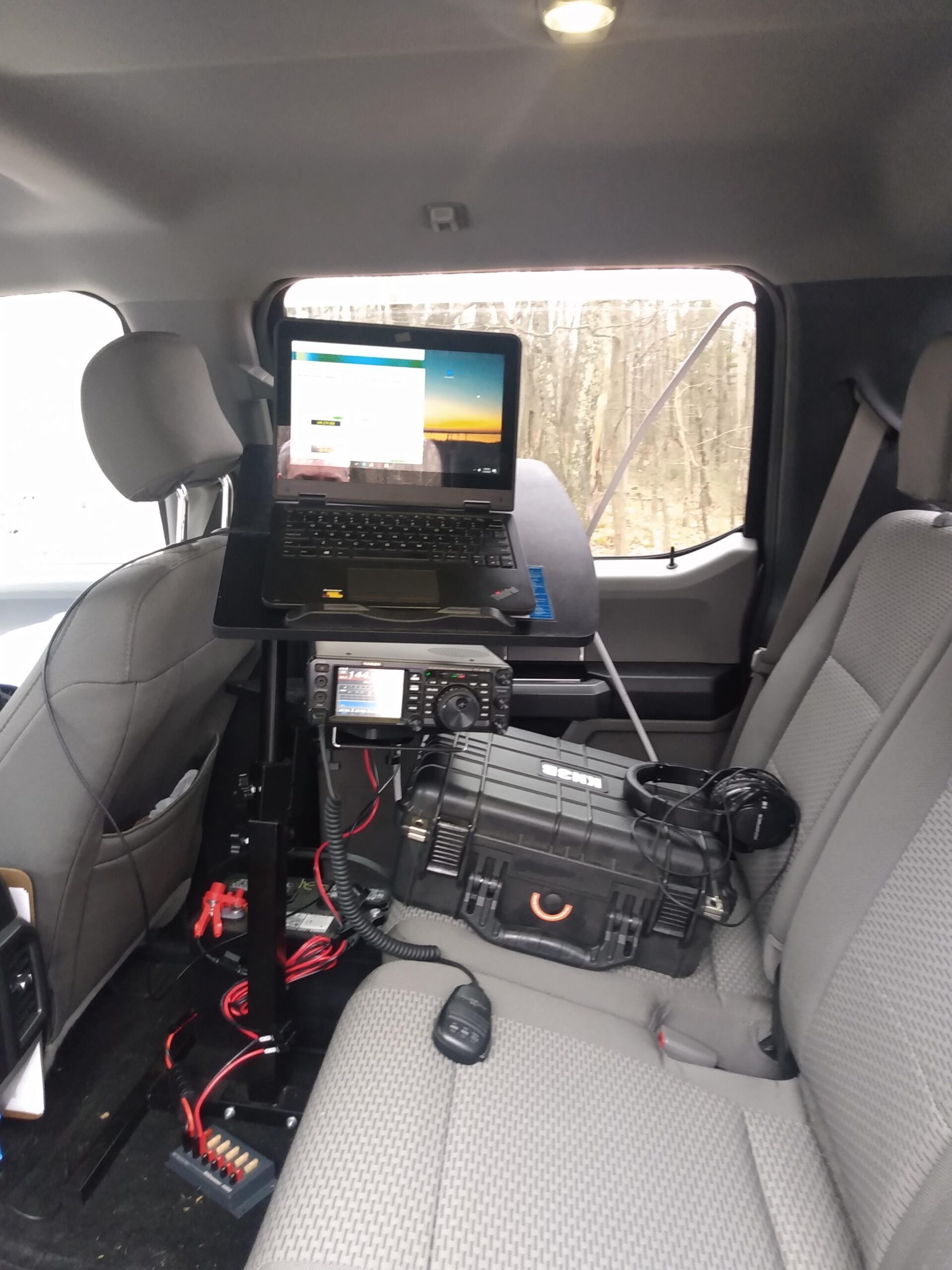
During the June VHF contest, I’ll set up a tent and a table and some chairs. January is a pretty unpleasant time to be outdoors in PA, so this time I decided to set up the operating position in the backseat of my truck. There is more than enough room for a small table, deep cycle marine battery, FT991a, and my laptop. I could run the heat in the truck and only have to get out to spin the beam.
The contest started promptly at 2PM. I was tuned to FT8 and immediately heard stations calling CQ. Dave KC3JNW was my first QSO on the very first contest-legal FT8 cycle. The first few minutes were a frenzy of the stations that could hear each other working each other, and it quickly slowed down.
I switched to SSB phone and worked a few stations, and then back to FT8 again. This cycle repeated a few times as the other stations moved between modes. I would hear a station on FT8, look them up on QRZ, point the beam in their general direction, and try to work them. I picked up a few stations this way.
A highlight of SSB phone was working Chris K2CR in two separate grid squares. As we had our second QSO, the clock struck 5PM and I decided it was time to pack up. My longest SSB QSO was either N2NT or K2CR at around 147 miles, and my longest FT8 QSO was to VA3IKE at 295 miles. Total was 27 FT8 QSOs (including a couple dupes) and 7 SSB QSOs, all on 2 meters. I am satisfied with these numbers.
Most FT8 QSOs were made with 25 watts, all SSB QSOs were made with 50w (maximum power on 2 meters with the FT991a). My deep cycle battery is a year old and does dip below 12v under load, but it had more than enough capacity to run the radio for 3 hours. I should start planning for its replacement.
I returned home at about 6PM and failed to make any QSOs on 6 meters. So I ended my evening casually S&Ping some NAQP SSB traffic on 20 and 40 meters.
One improvement I would like to make is adding an antenna switch and an omnidirectional 2 meter antenna. Working with only a beam can be difficult, and I don’t know how many stations I wasn’t hearing due to possible nulls in the pattern. I will ponder the antenna situation and come up with new experiments for June VHF.
I own a few antique AM broadcast radio receivers through unfortunate side effects of being a ham, but I’ve never repaired one. I’ve seen them in Pennsylvania antique malls, but never tried a repair or restoration myself because I didn’t think I was capable. After becoming a fan and subscriber of Mr Carlson’s Lab on Youtube, I had warmed up to the idea of buying one and giving it a shot.
If you’ve never been to a central PA antique mall, they are lousy with junk that people think is worth its weight in gold. Cast iron cookware is especially overpriced due to this phenomenon (and its weight), and I’ve bought and sold enough cast iron pans to stop treating them as an investment. But antique AM radios are ever-present, and a lot of them are very affordable. Seems like nobody is able or willing to take the time and effort to restore them. Probably because nobody wants to buy them after they are fixed. AM radio is basically dead anyway, right?
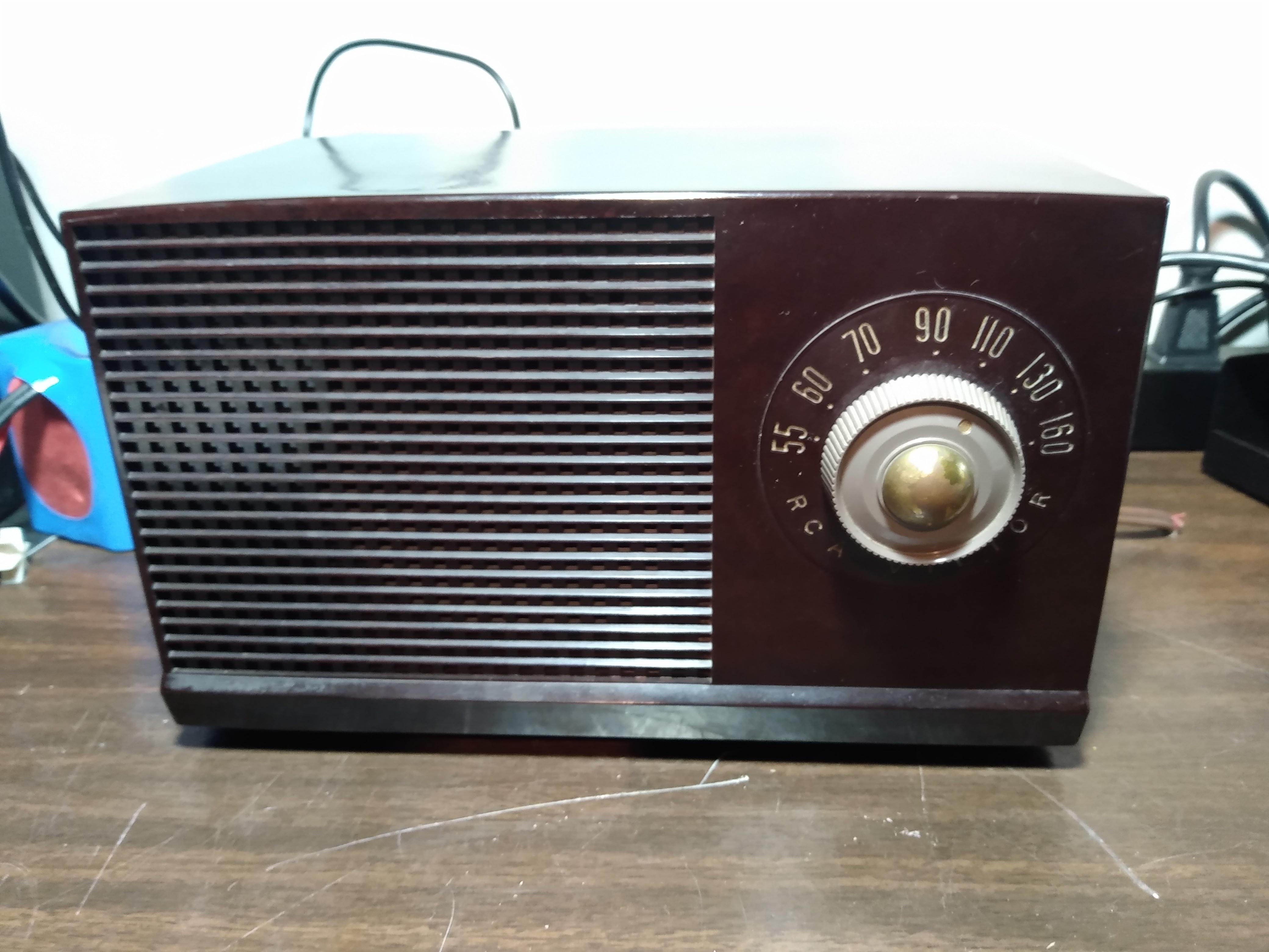
Quite a while ago I was in one of these antique malls with my wife and I found this RCA Victor from 1953 for $25. It was in very good shape on the outside, all the knobs moved as they should with no problems, and the original “instruction” sheet (I think the most accurate comparison would be the “tag” on a mattress today) was still on the bottom of the radio. I didn’t have the tools at the time, or the permission from the seller for that matter, to remove the back and peer inside. But for $25, it would make a good conversation piece. I bought it without further question.
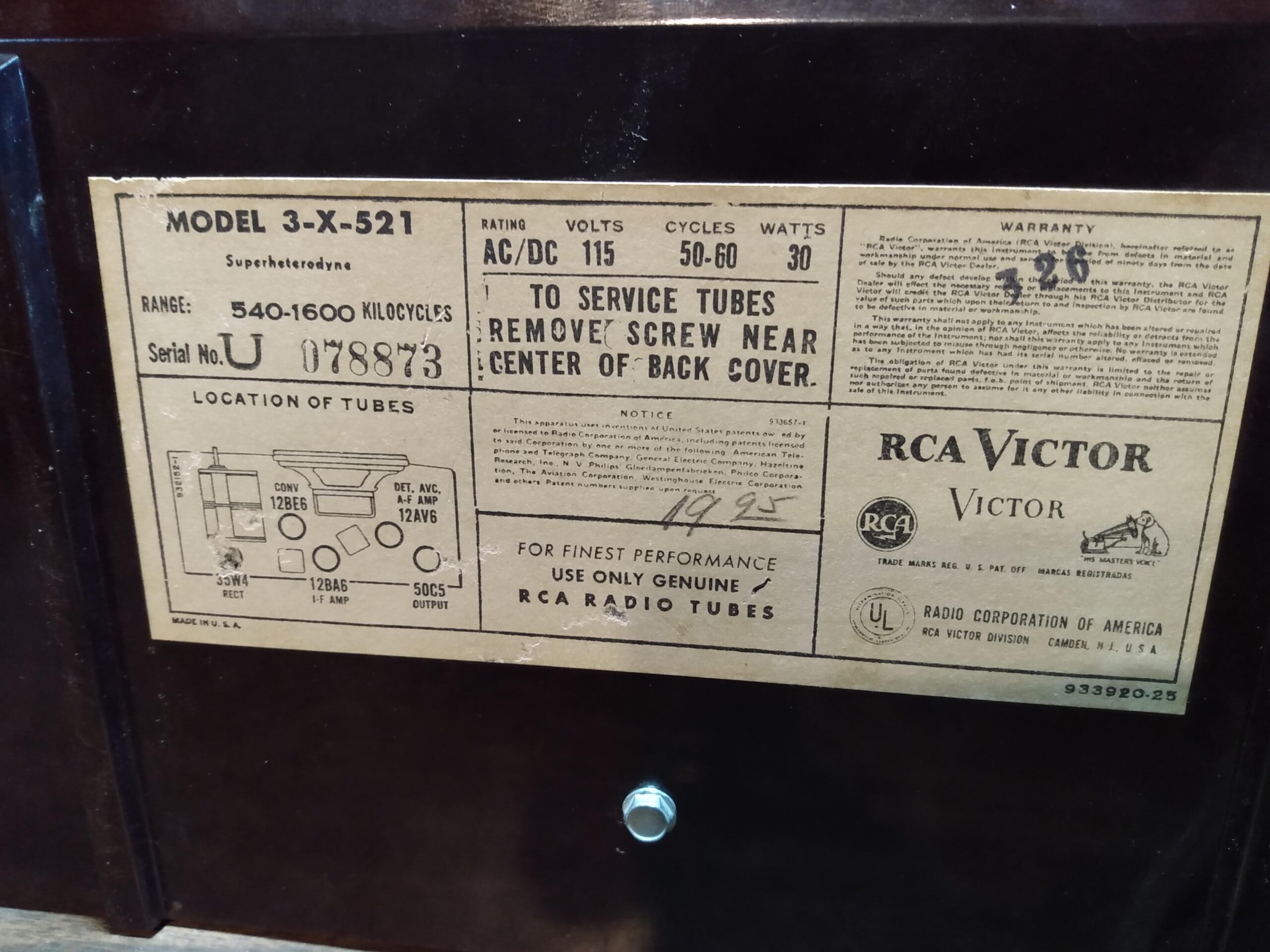
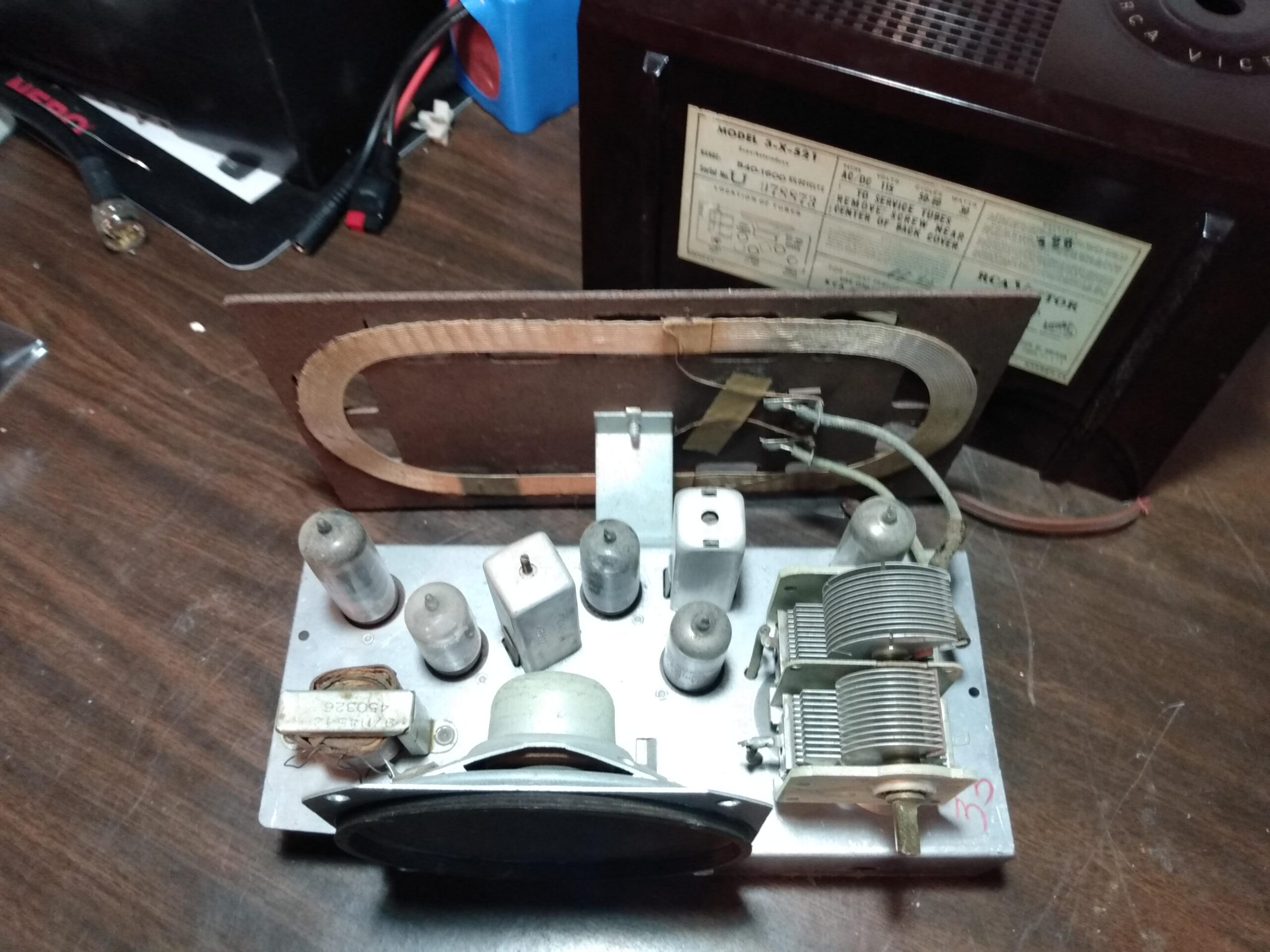
It was an RCA Victor Model 3-X-521. The power cord was dry and cracking under the slightest bit of stress, meaning it couldn’t be plugged in until that was replaced. There was some flaking of the tuning knob paint, but that wouldn’t affect anything. But the good news: Everything mechanical worked without any physical resistance and there was no obvious damage that indicated water or neglect. With any luck, it would be a great candidate for a simple restoration. I got it home, put in on the bench, and cracked it open. It was 100% original and no rust was present. So of course, I put it on a shelf on top of another old radio and said to myself, “I will fix this someday.”
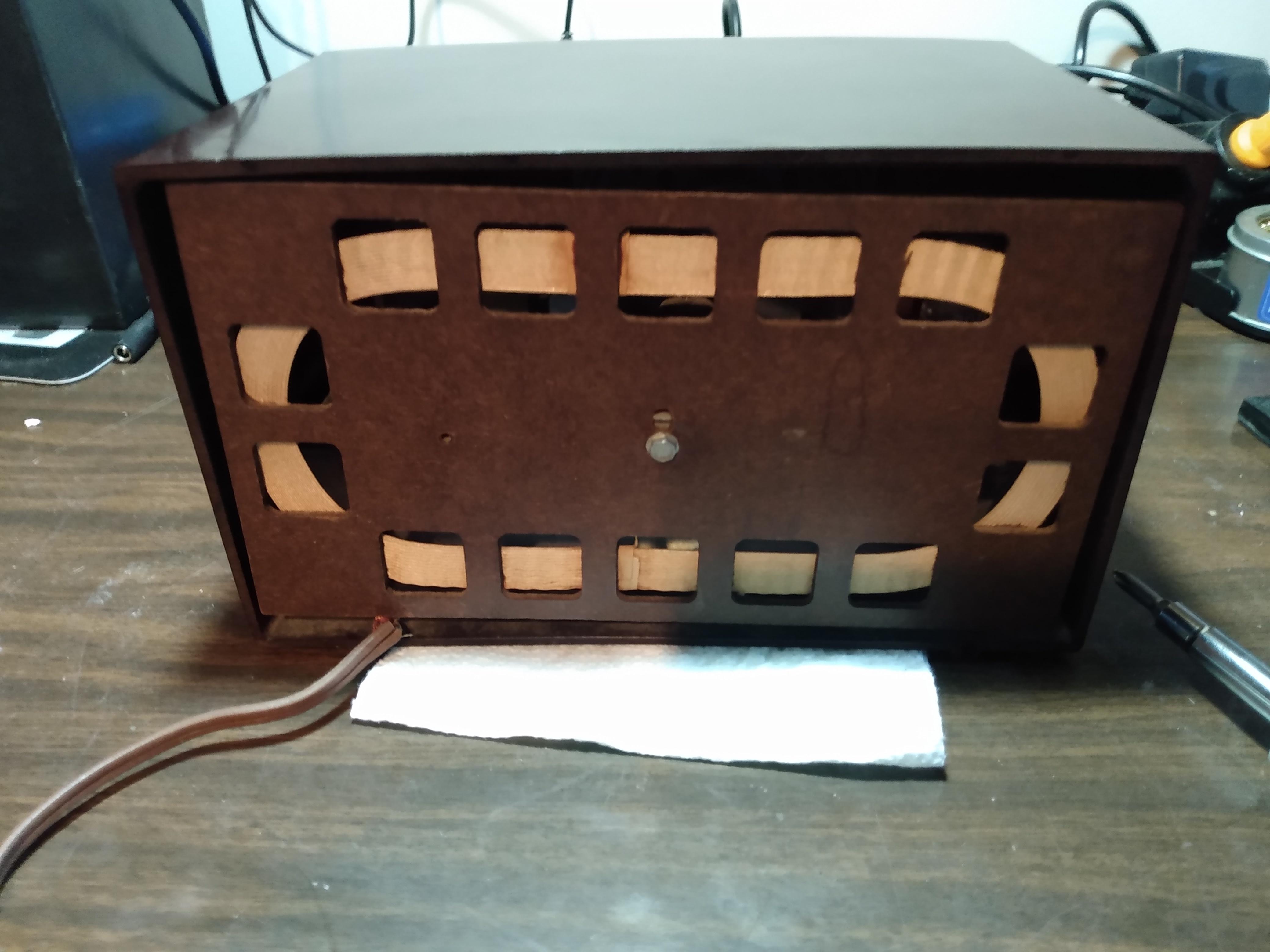
FrontRear showing antennaUser manual on bottom
Life tends to get in the way of a lot of my hobbies and projects. It’s taken a while, but I’ve learned to accept this. I usually get to the projects I really want to complete. About a year passed, and only after acquiring a few tools (variac, mostly) and some experience (lots of soldering), I was ready to tackle a very simple restoration of a radio with very few components.
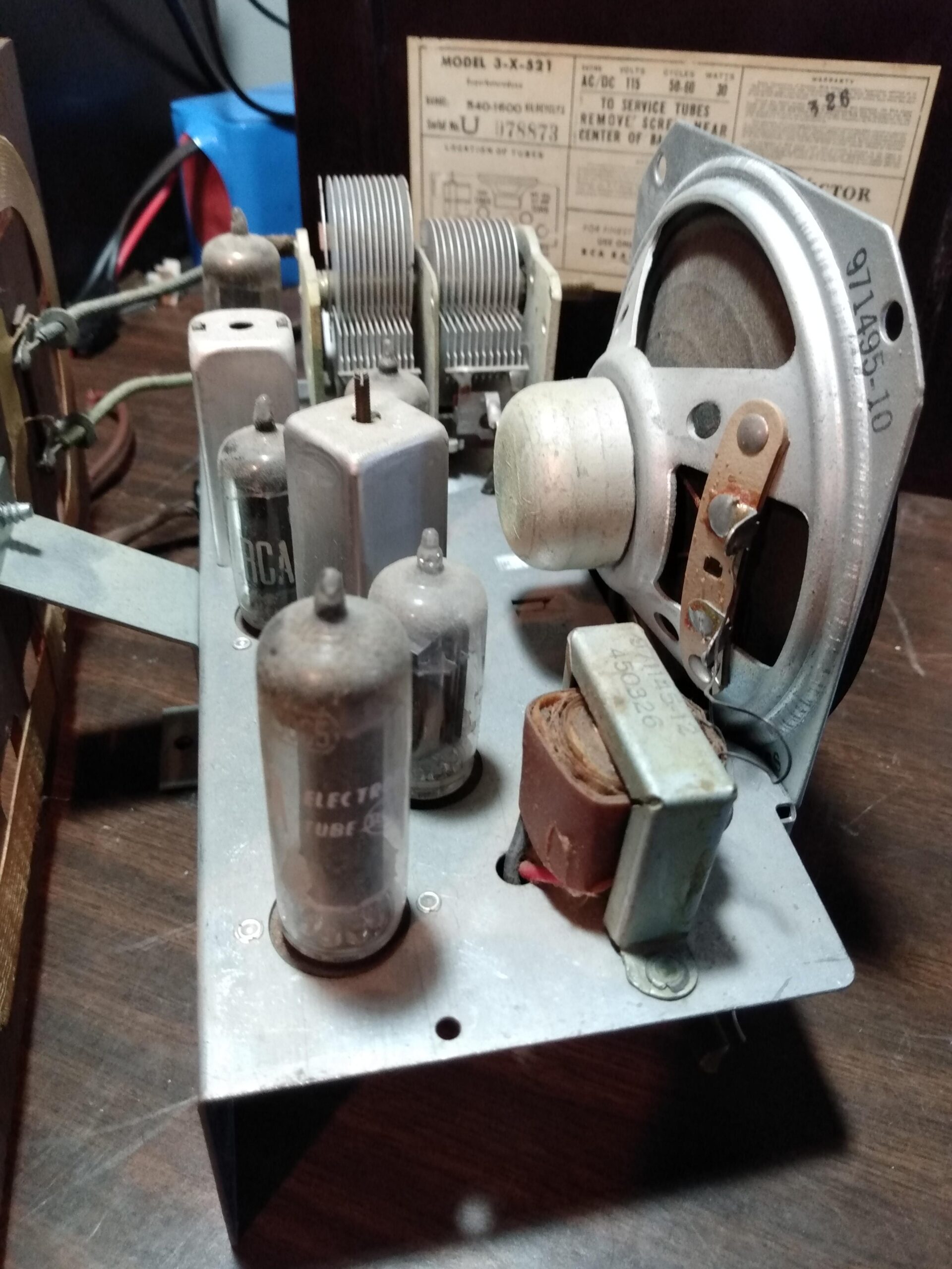
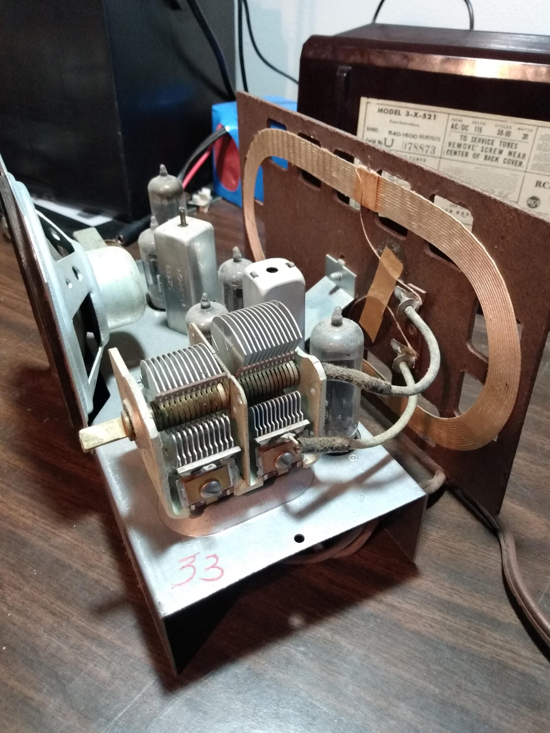
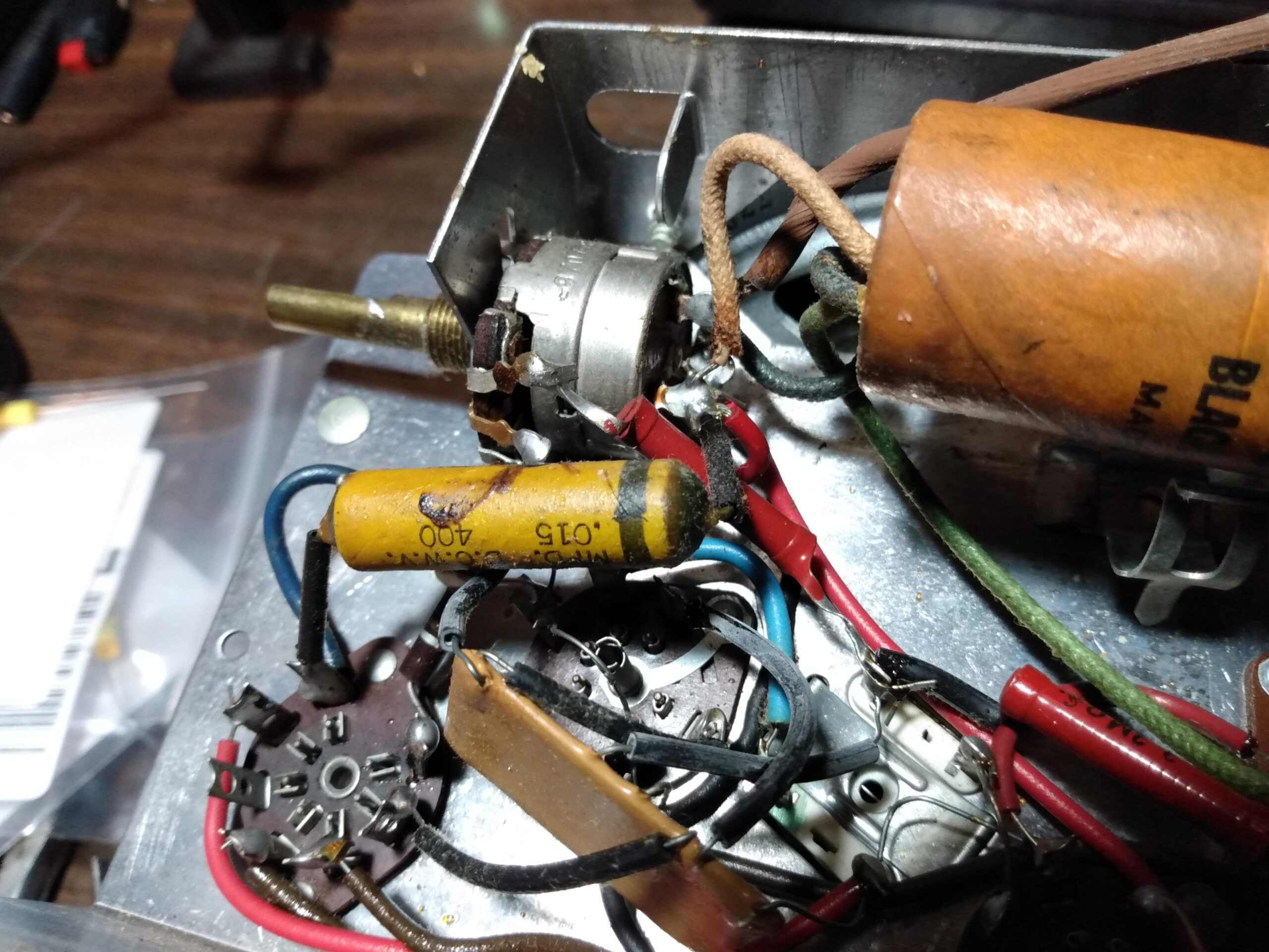
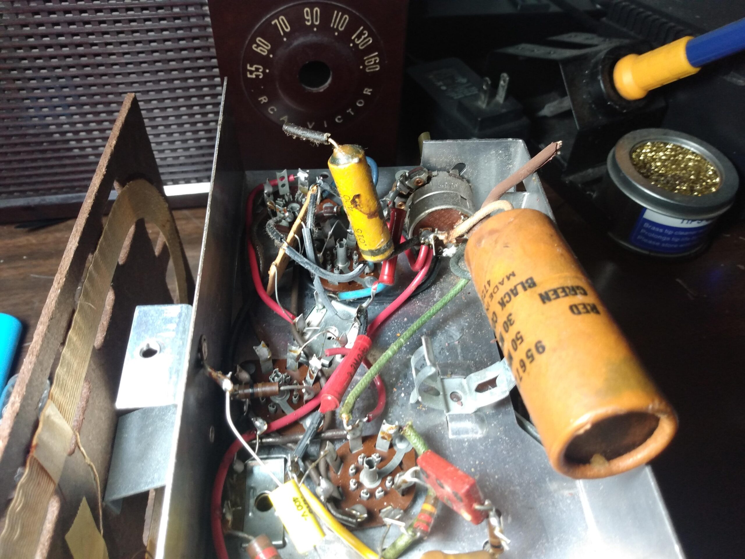
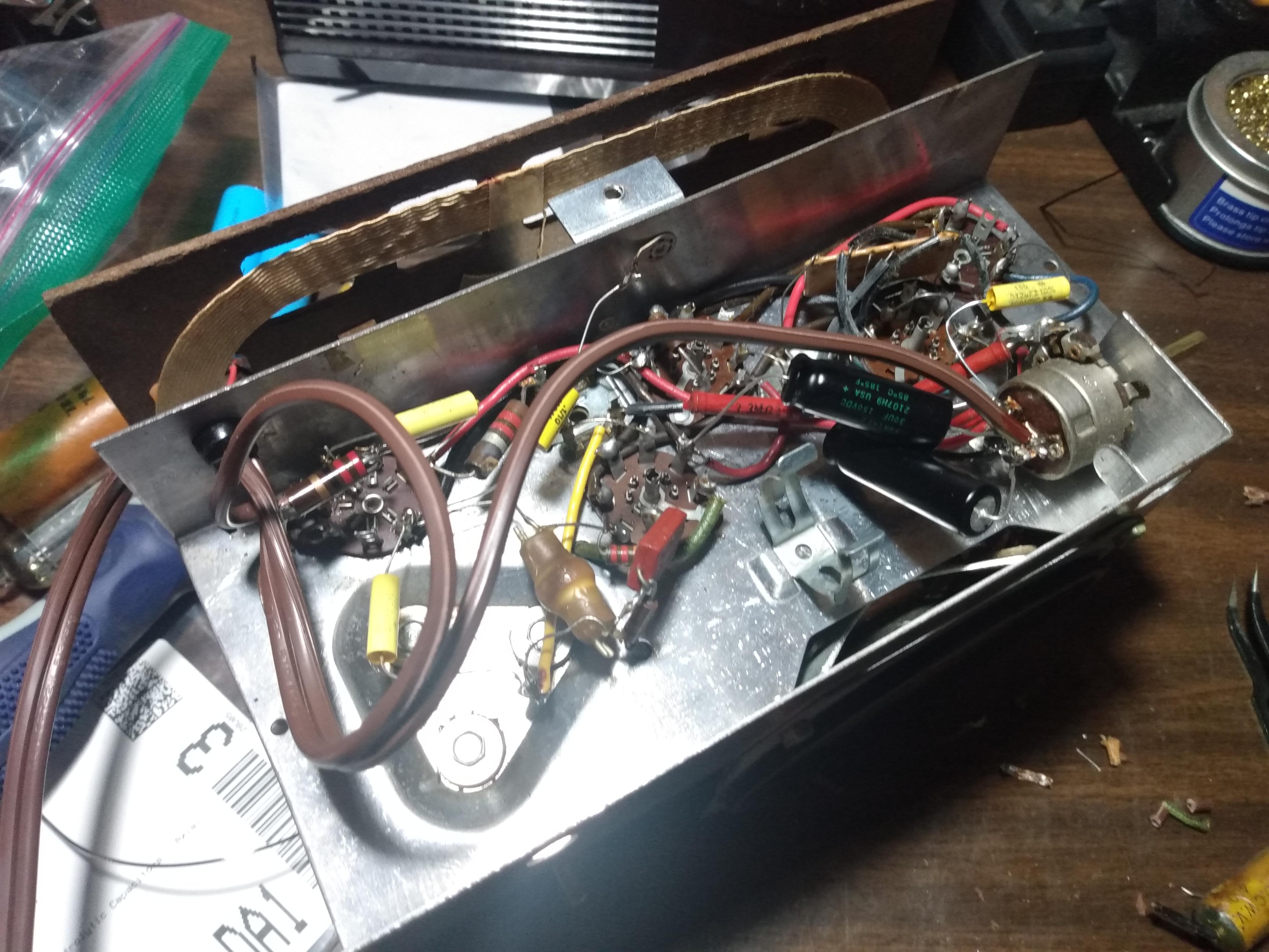
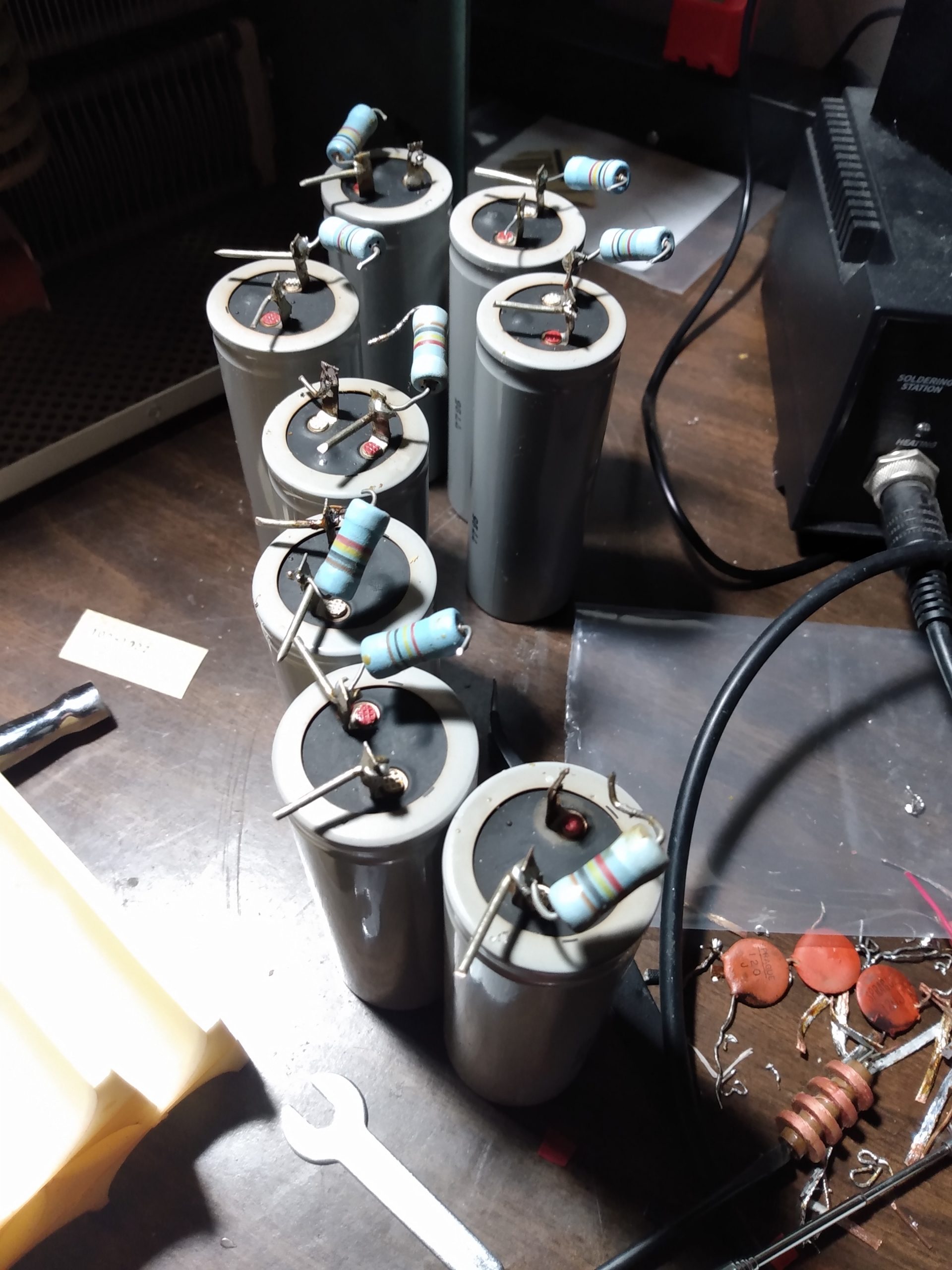
Interior top viewSpeaker and audio transformerTuning capacitor
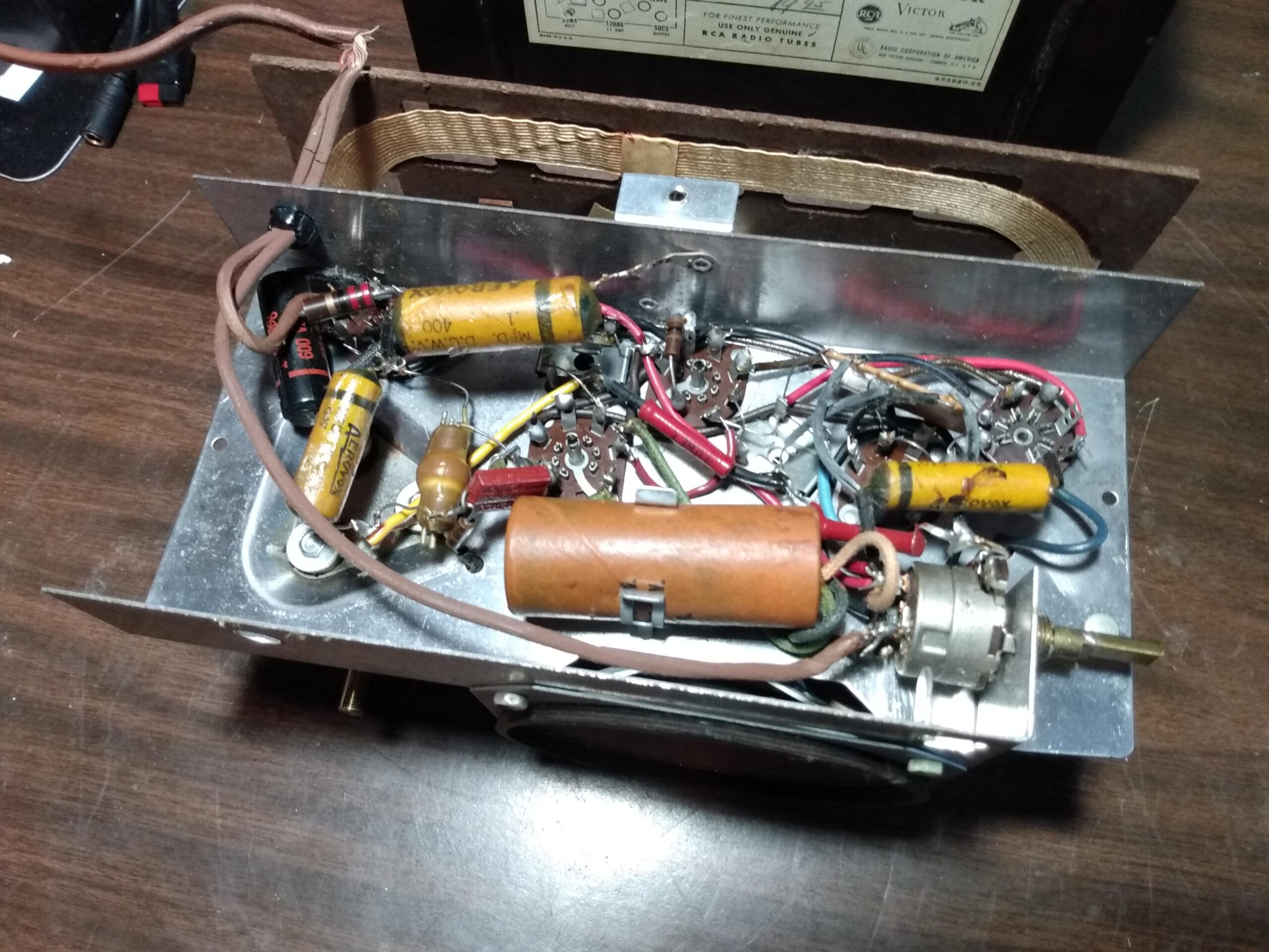
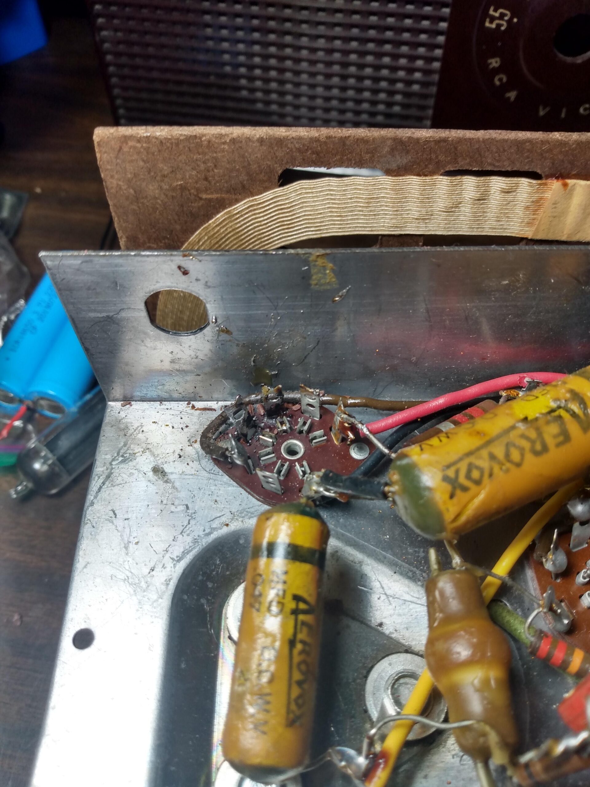
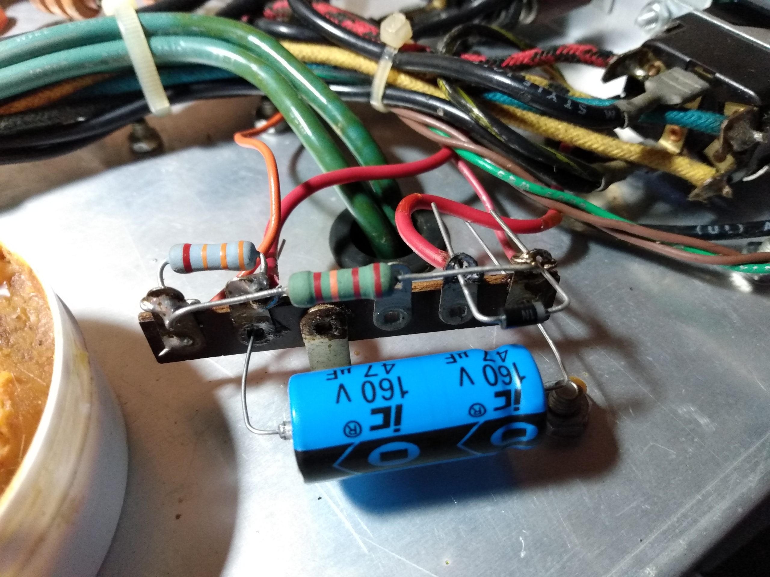
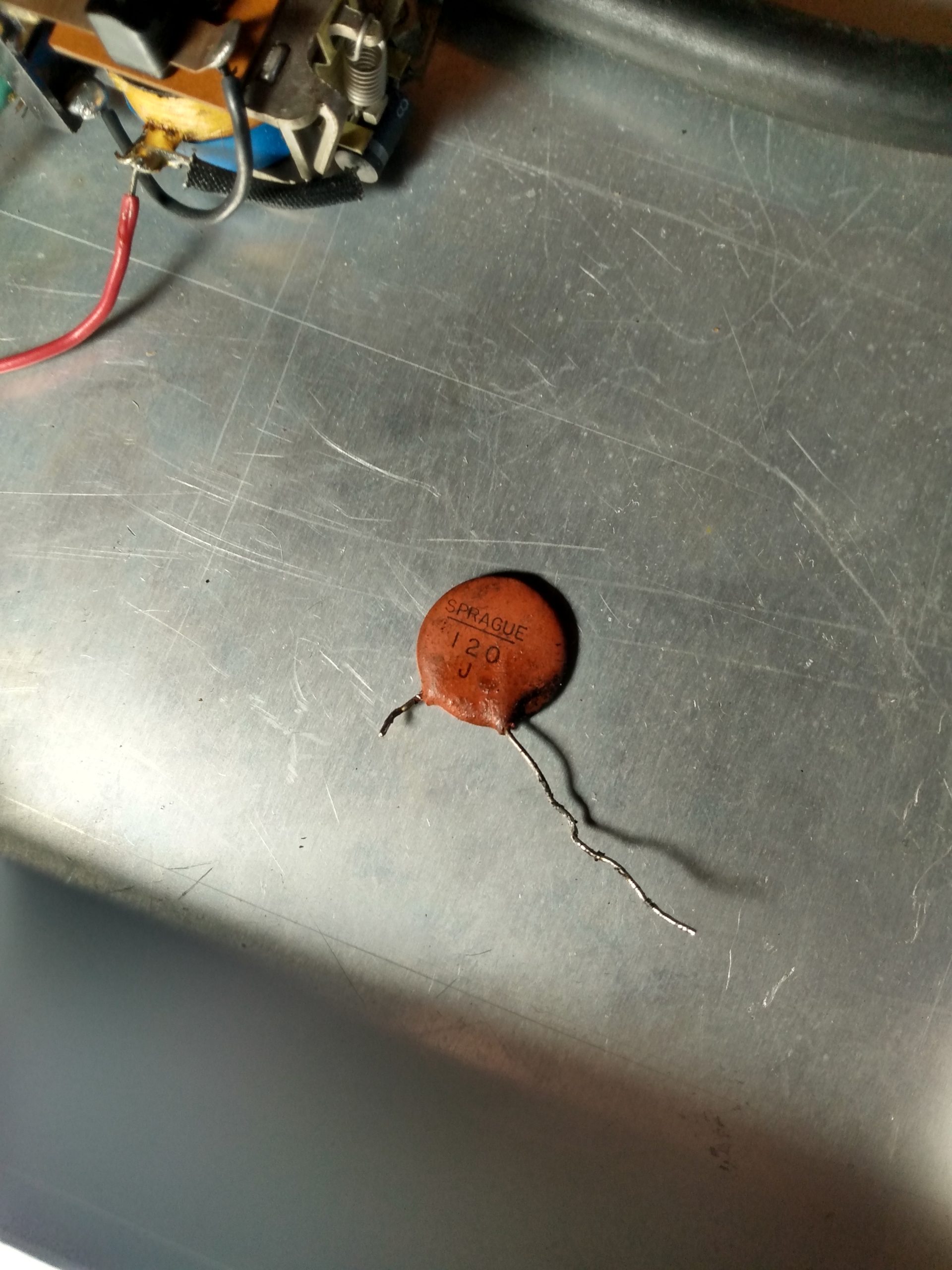
The interior condition of the radio is on par with the exterior. Some dust, but otherwise original and undamaged. The tuning capacitor was very clean and straight. Flipping the radio over, you can see that it was completely original. Clearly visible are four wax paper capacitors, and a “multi-section cardboard” capacitor that contained two polarized capacitors of different values. All of these capacitors need to be replaced no matter how they test. They are well past due at about 70 years old.
UndersideOn/off/volume switchPower cable
I wasn’t able to plug the radio into my new Chineseium variac because of the disintegrating power cable, so I didn’t know if the radio worked at all, and I didn’t want to add a power cable before I had all the usual suspects (capacitors) replaced anyway. The condition of the radio, originality of the parts, and lack of any obvious catastrophic failure gave me optimism that the radio would work after I did the bare minimum.
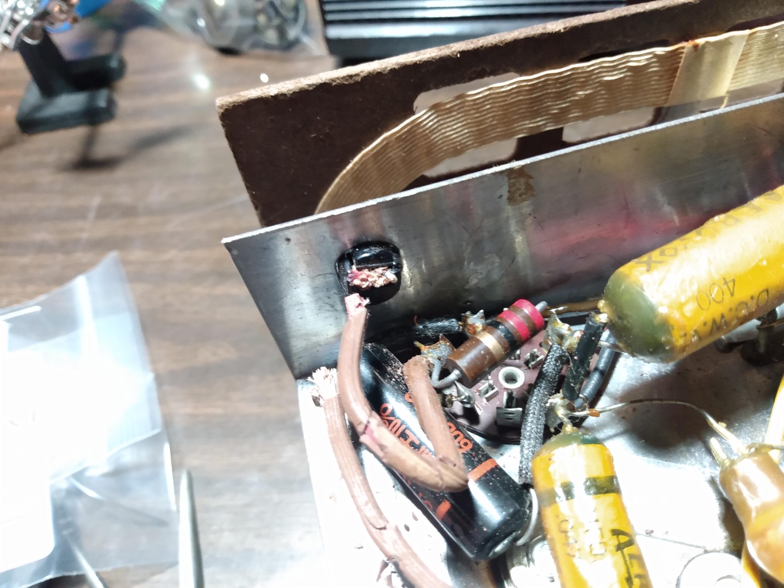
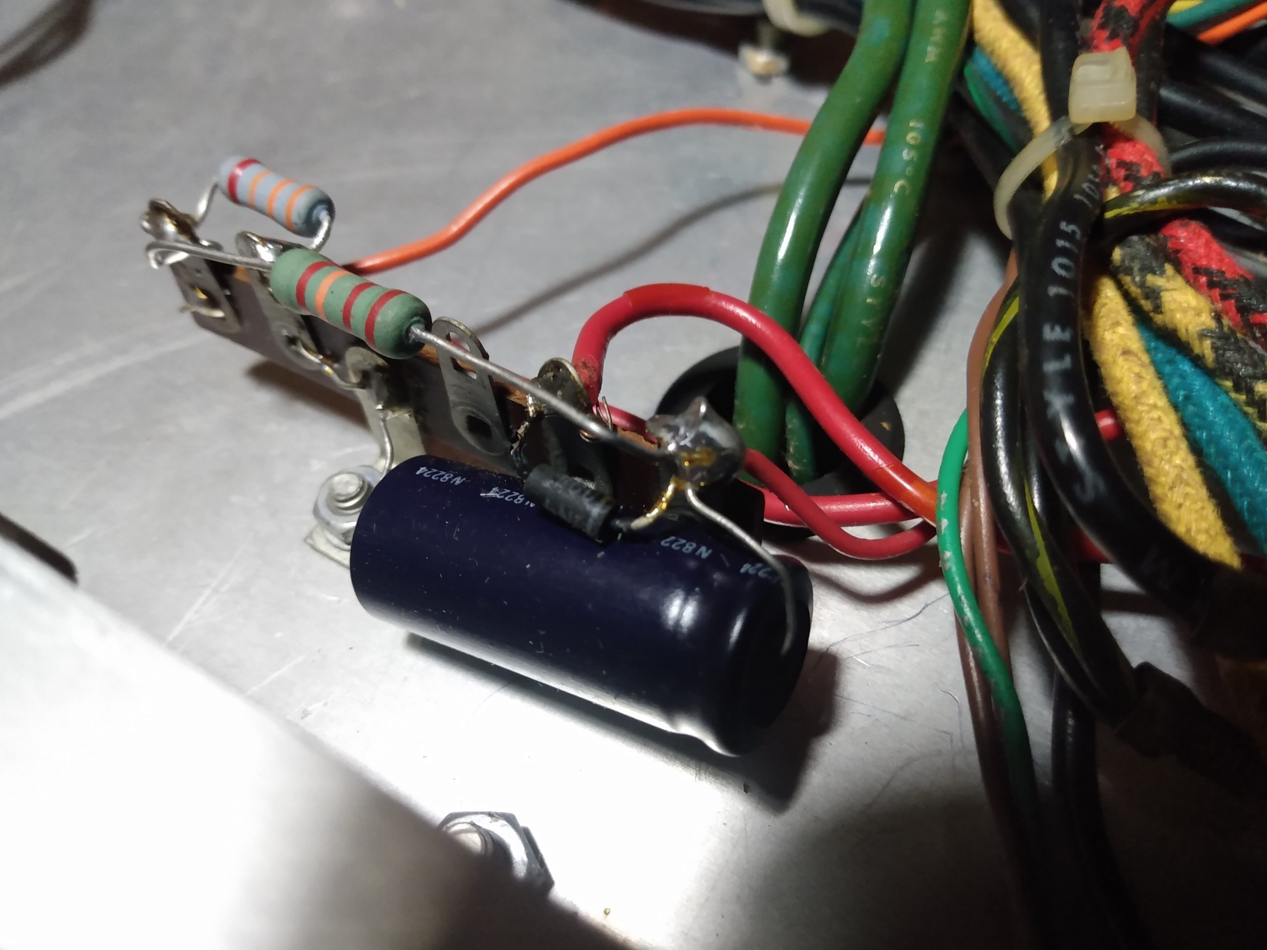
I began by removing the power cord by cutting it on either side of the chassis and removing the grommet. I left short leads in place so I knew where the new power cord needed to go. This took a while, it didn’t want to give up the grommet. The leftover lead on one side of the power cord would not stay in place for long, because it got in the way of removing the first .5MF capacitor.
There was an immediate lesson learned at this point in the old capacitor removal process. This radio doesn’t have a PCB, because they didn’t exist in 1953. Everything is point-to-point wiring, and most points are on a pin connected to a tube socket. Using solder wick to remove the old solder heated up the sockets to the point where the pin would start to wiggle, meaning something was melting just enough to allow for that movement. The lesson here: Just clip the leads of the old components, making note where everything was connected, and then clean up the terminals on the tube socket when everything is out of the way. This minimizes the heating time on the tube socket and decreases the likelihood of melting something that shouldn’t be melting. The old capacitors are useless anyway, no need to preserve their lead length.
So the first .5MF capacitor and one side of the AC power line were removed. A resistor shared the same terminal as the AC line on one side, and the .5MF capacitor on the other side. I completely removed it so I could get a better look at the socket, making sure to note where everything was connected.
Before removalBefore removal (angle 2)AC power, resistor, capacitor removed
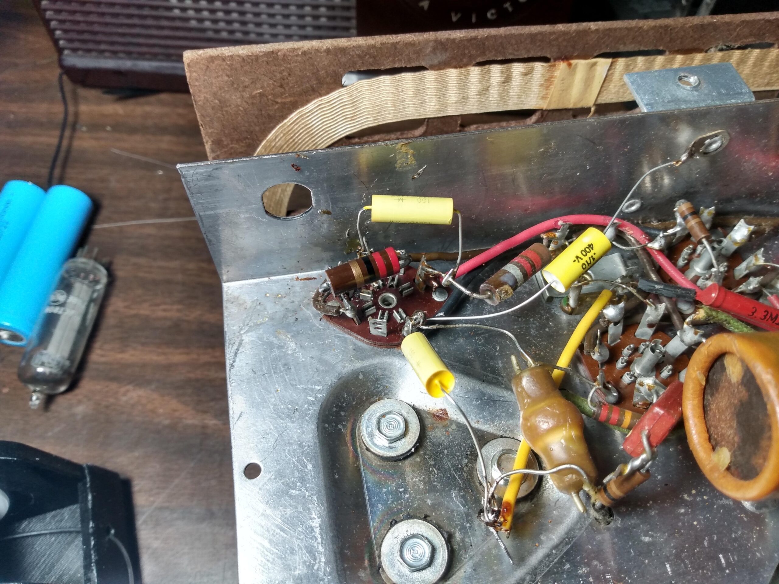
The replacement capacitors were a lot smaller than the original wax paper capacitors, which made dealing with the point-to-point wiring a little bit easier. The first three capacitors were closely located, so after replacing the first I ended up replacing the next two at the same time. This process didn’t take as long as the first because I just clipped the leads and cleaned the terminals up without the capacitor in the way.
First capacitor replacedThree capacitors replaced
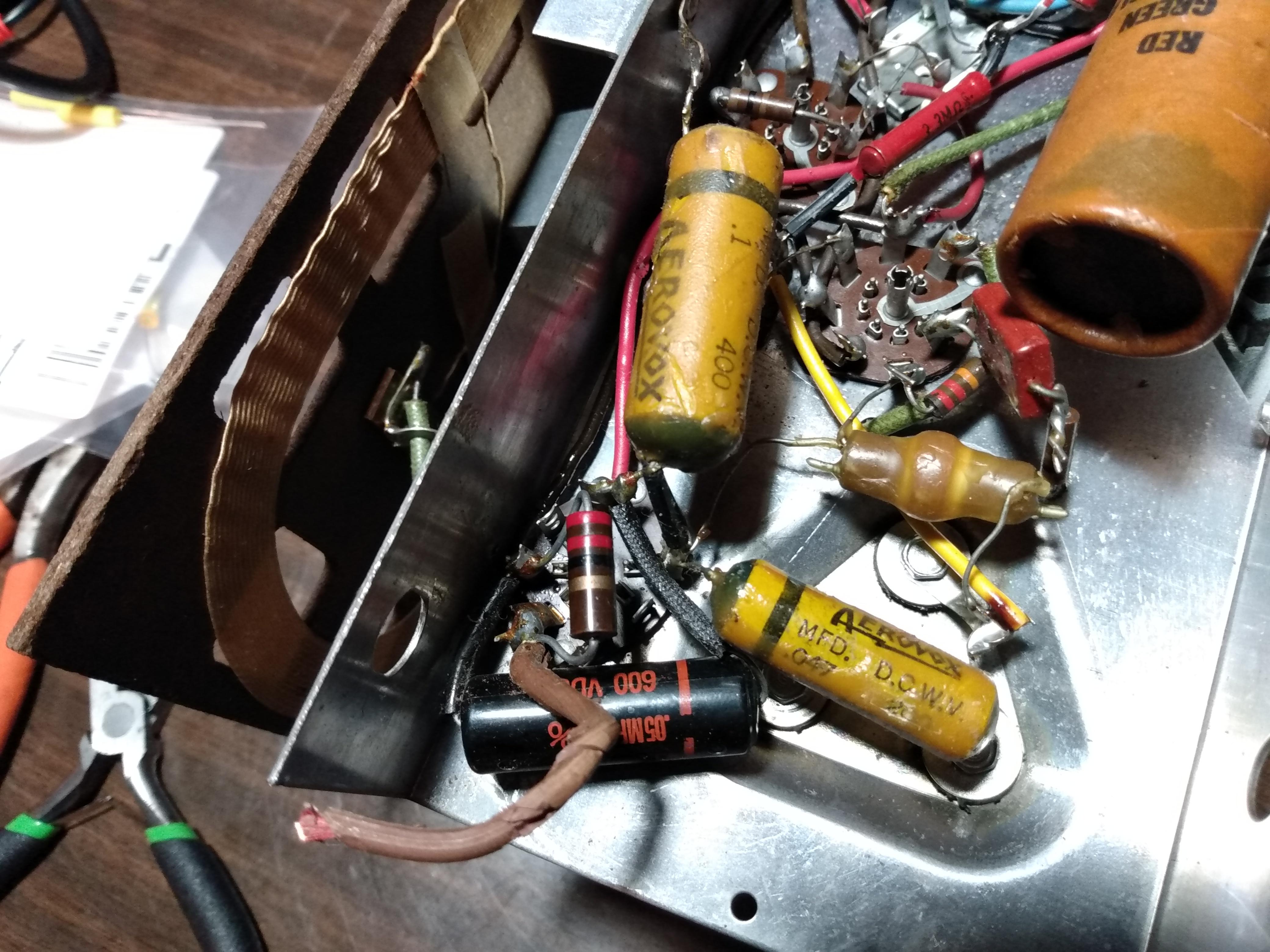
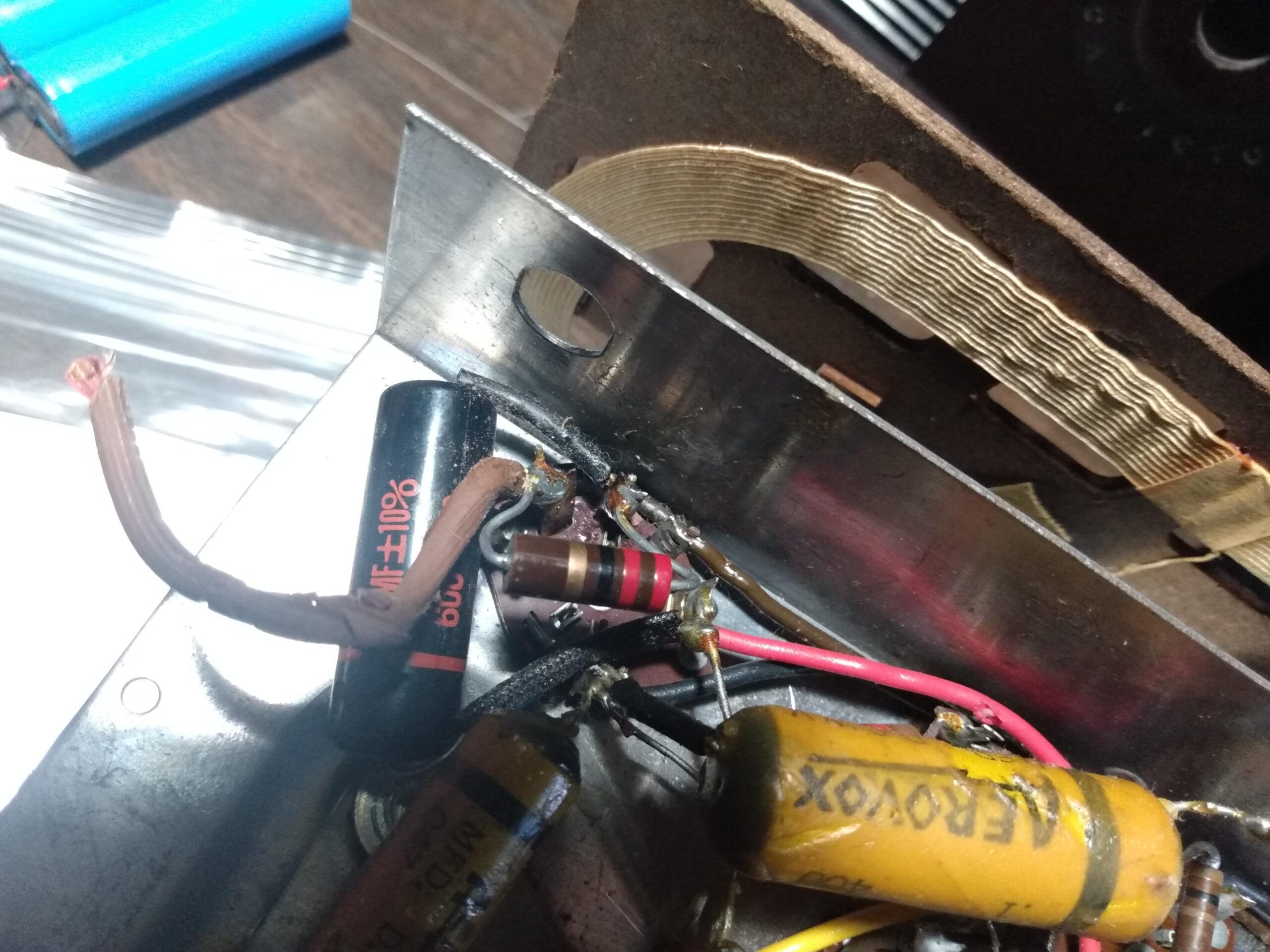
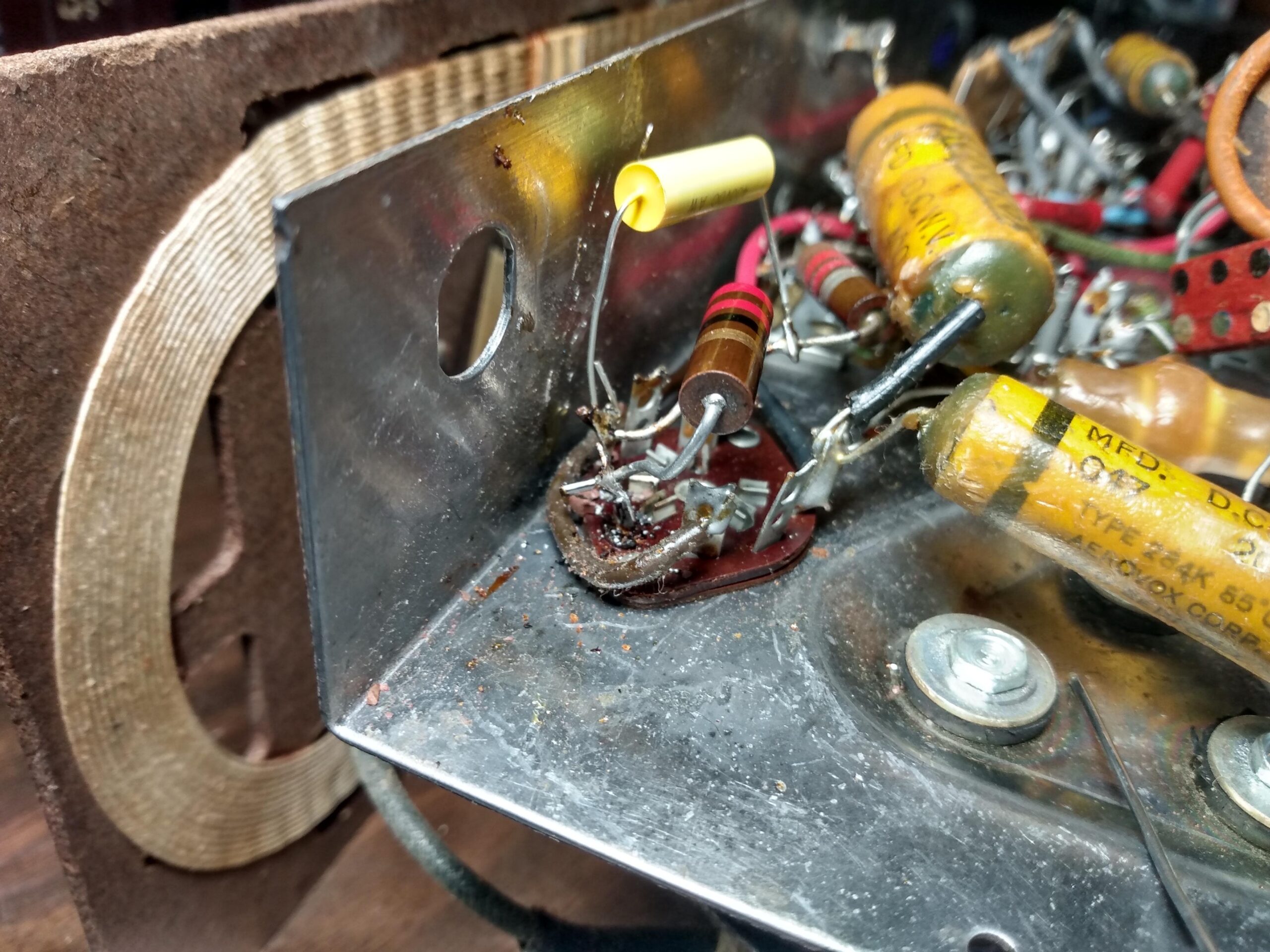
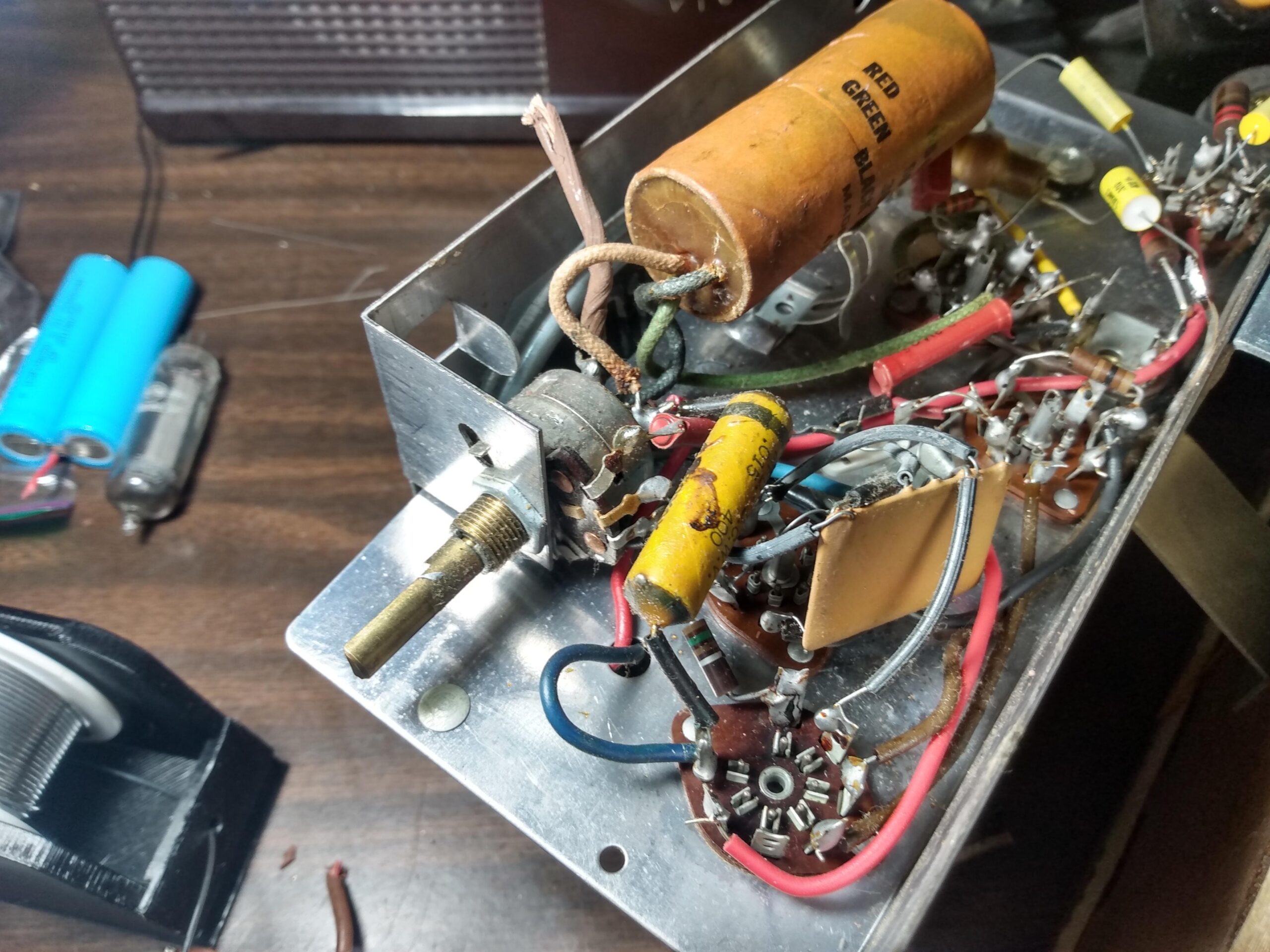
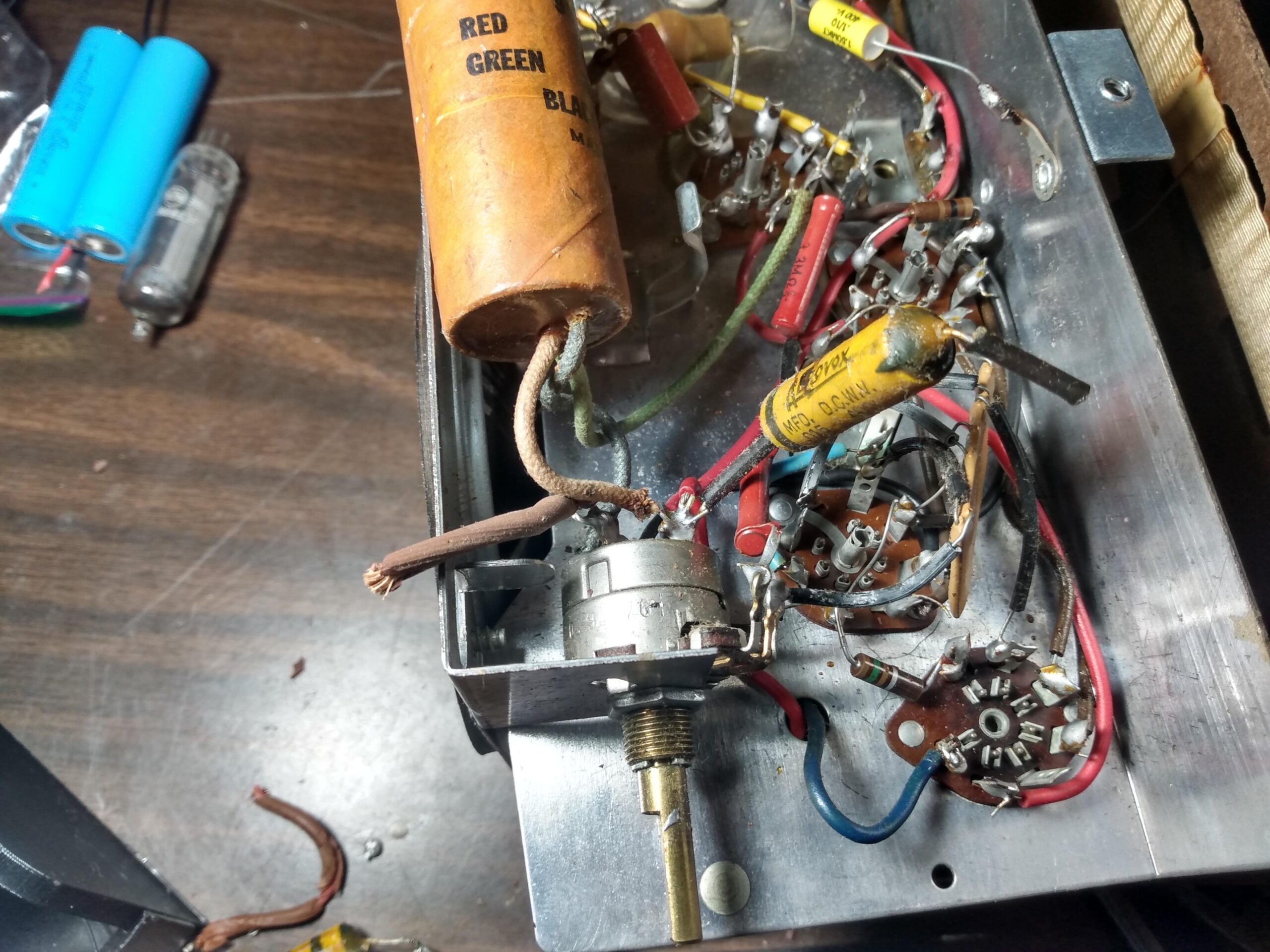
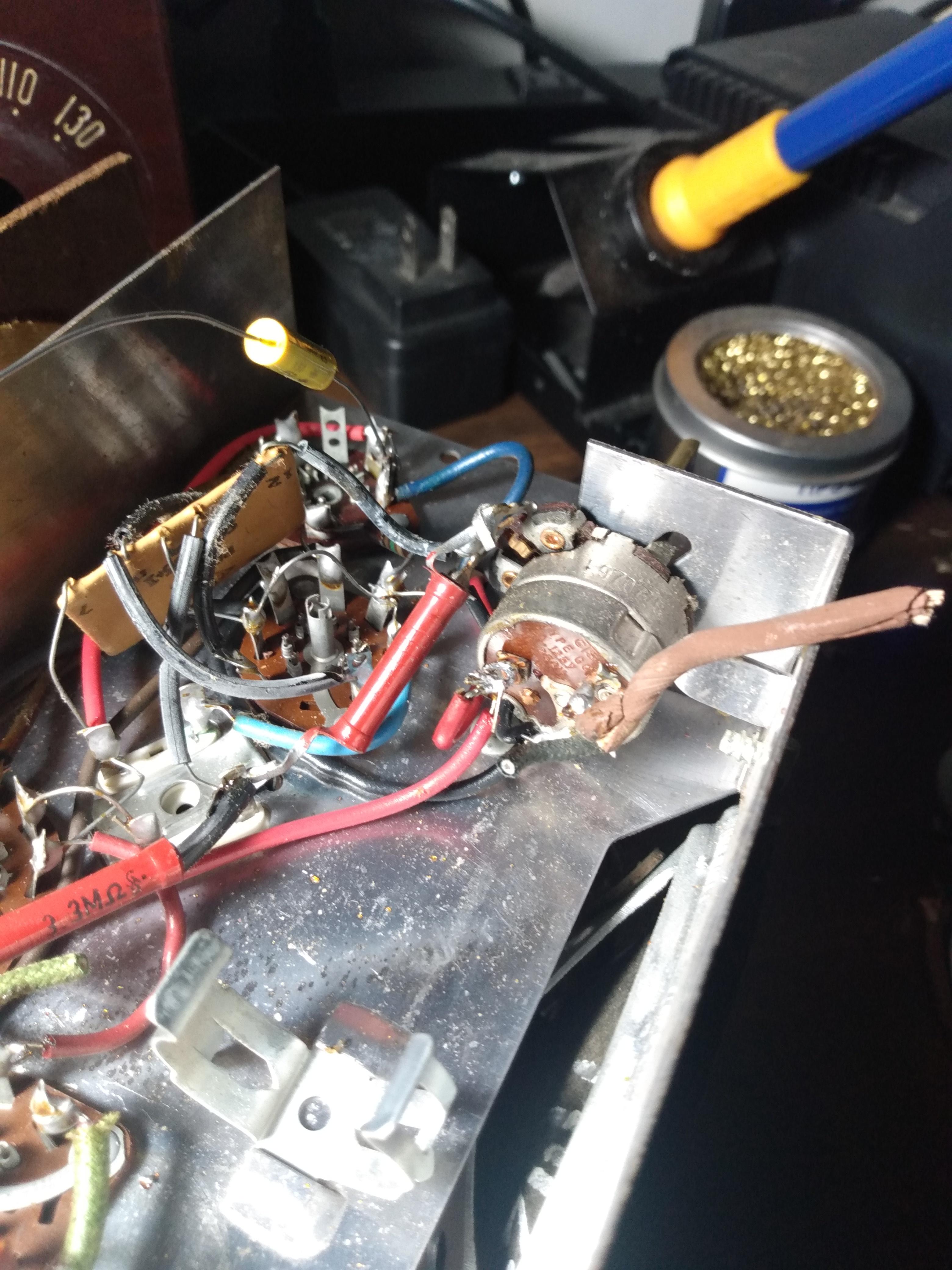
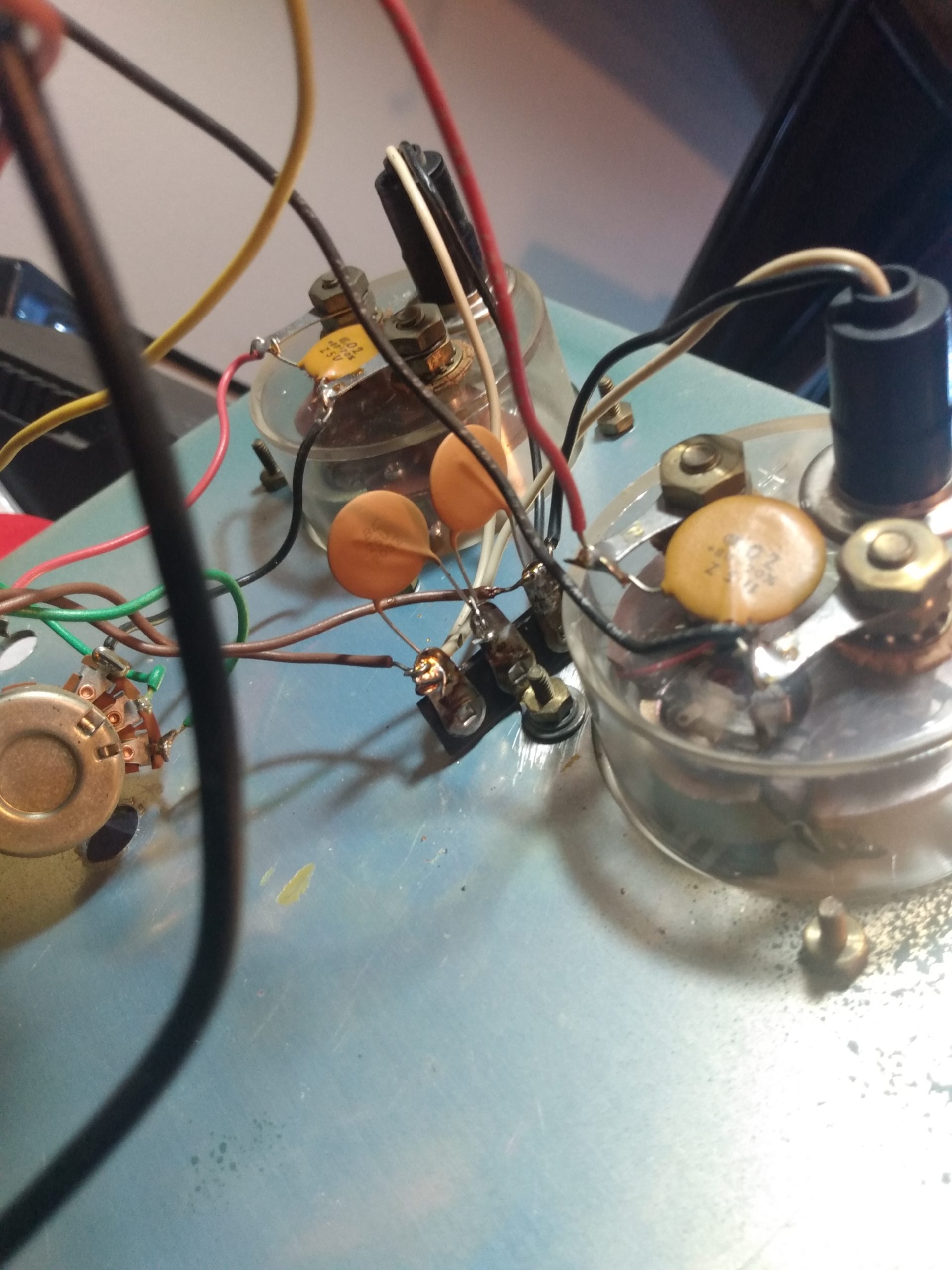
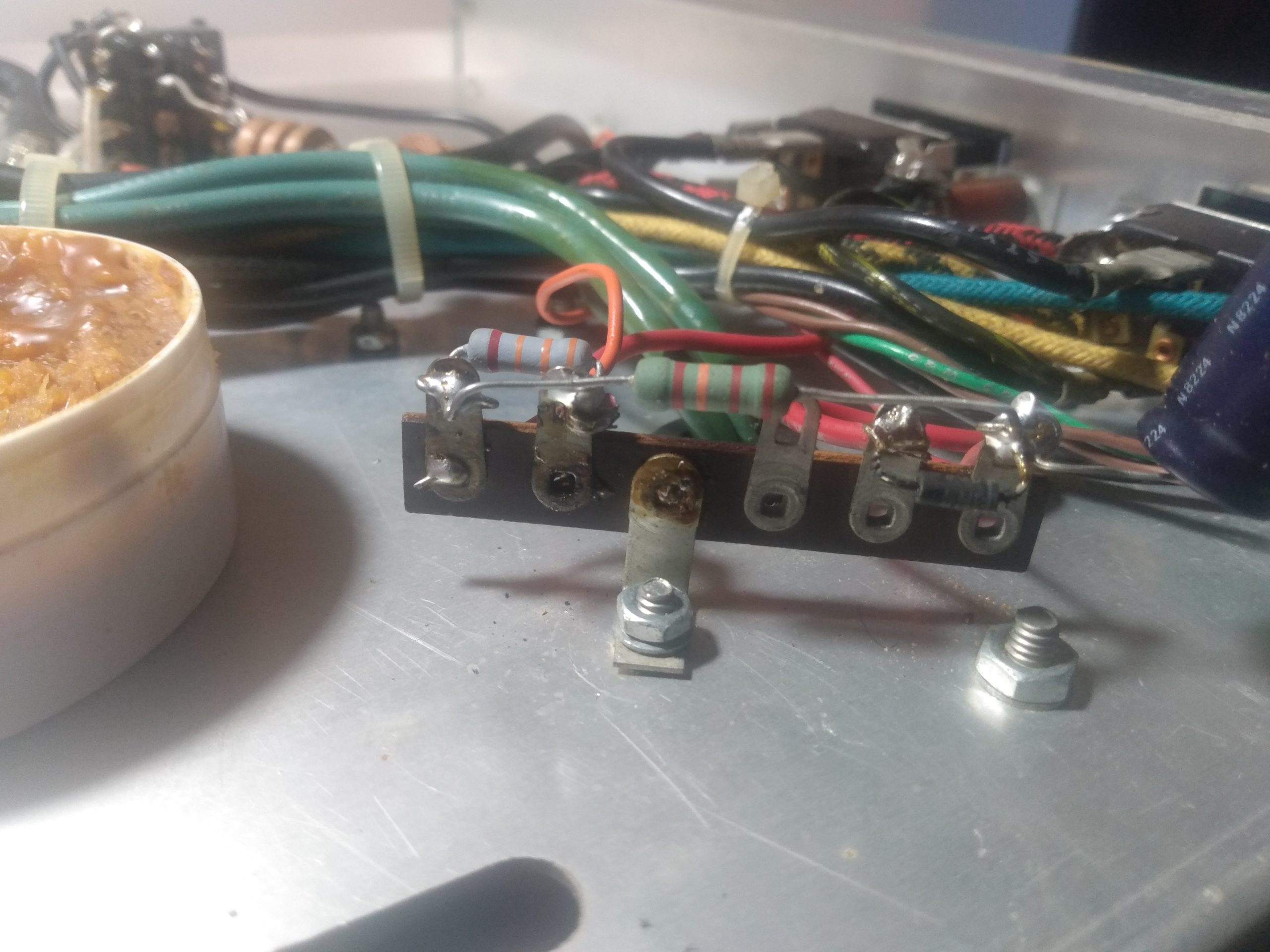
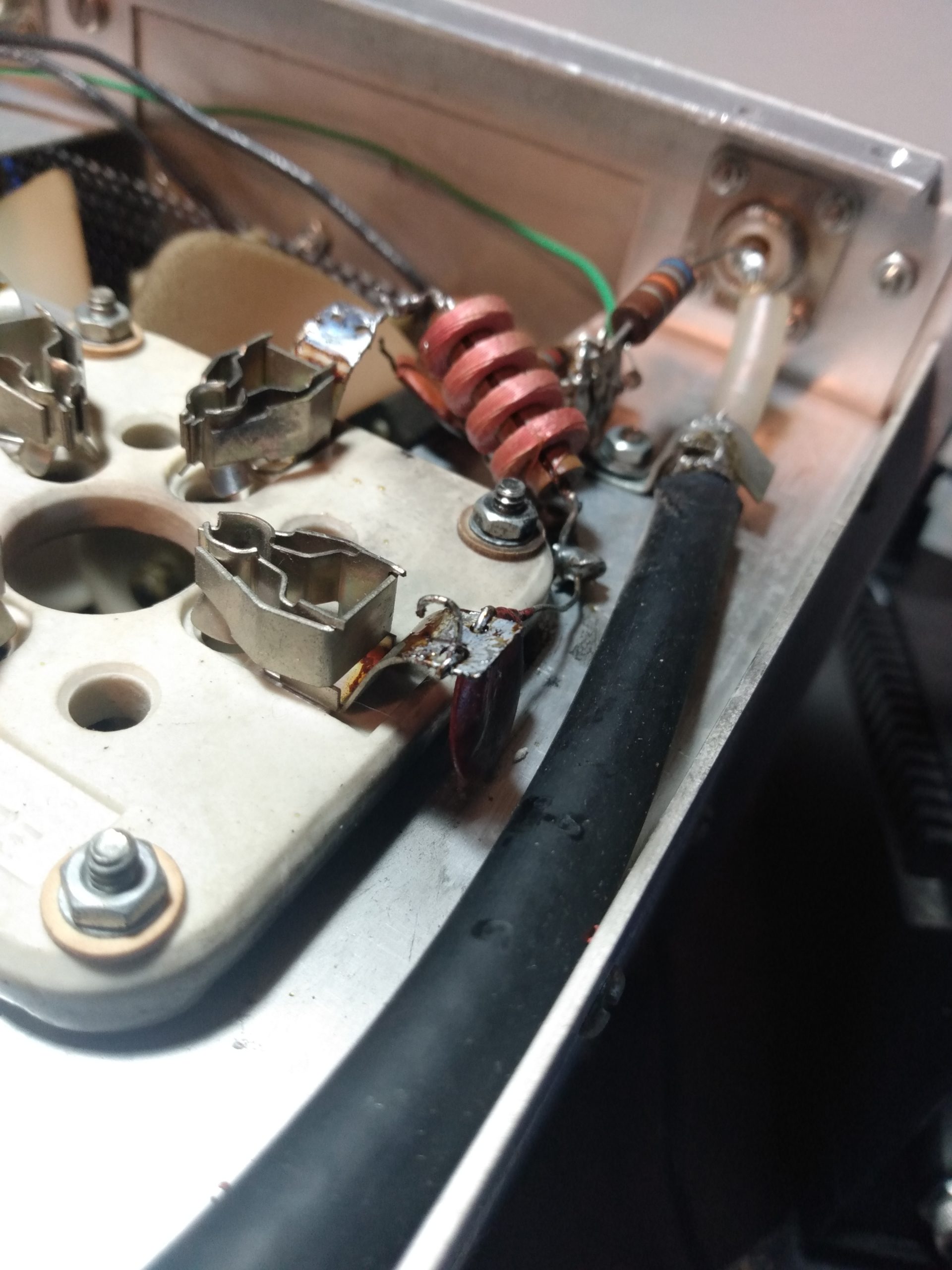
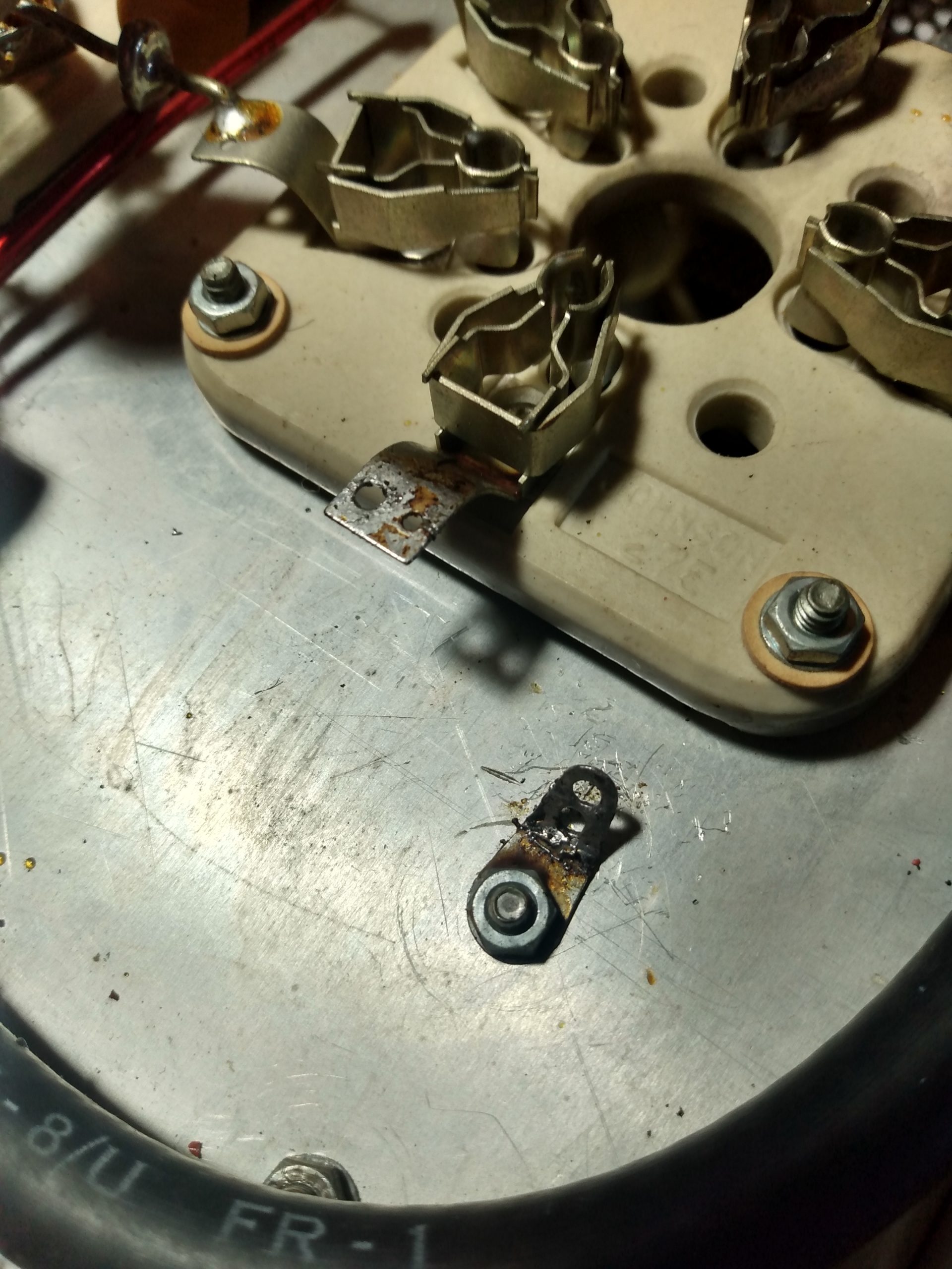
I turned my attention to the wax paper capacitor on the other side of the radio, and the multi-section cardboard cap that shared the on/off/volume switch. This was a crowded part of the radio, so I took several pictures from different angles. First I removed the .015MF wax capacitor, and replaced the unobstructed lead with one end of the replacement capacitor. This capacitor shared its other lead with other components on the on/off/volume switch, it would be soldered in place once all other connections were ready. I then removed the multi-section cardboard capacitor, making sure to leave enough of the color coded leads in places so I knew where they went.
Wax paper and cardboard capsLots of connectionsFinal photo before removal
The multi-section cardboard capacitor is actually two polarized electrolytic capacitors in one housing with separate positive leads and a shared negative. This was apparently a common thing back in the 1950s, and the solution to this is to just replace it with two modern electrolytic capacitors with the same values as the originals. It’s a good thing that the modern electrolytic replacements came with long leads, because they were necessary to get them both to fit without shorting to the chassis.
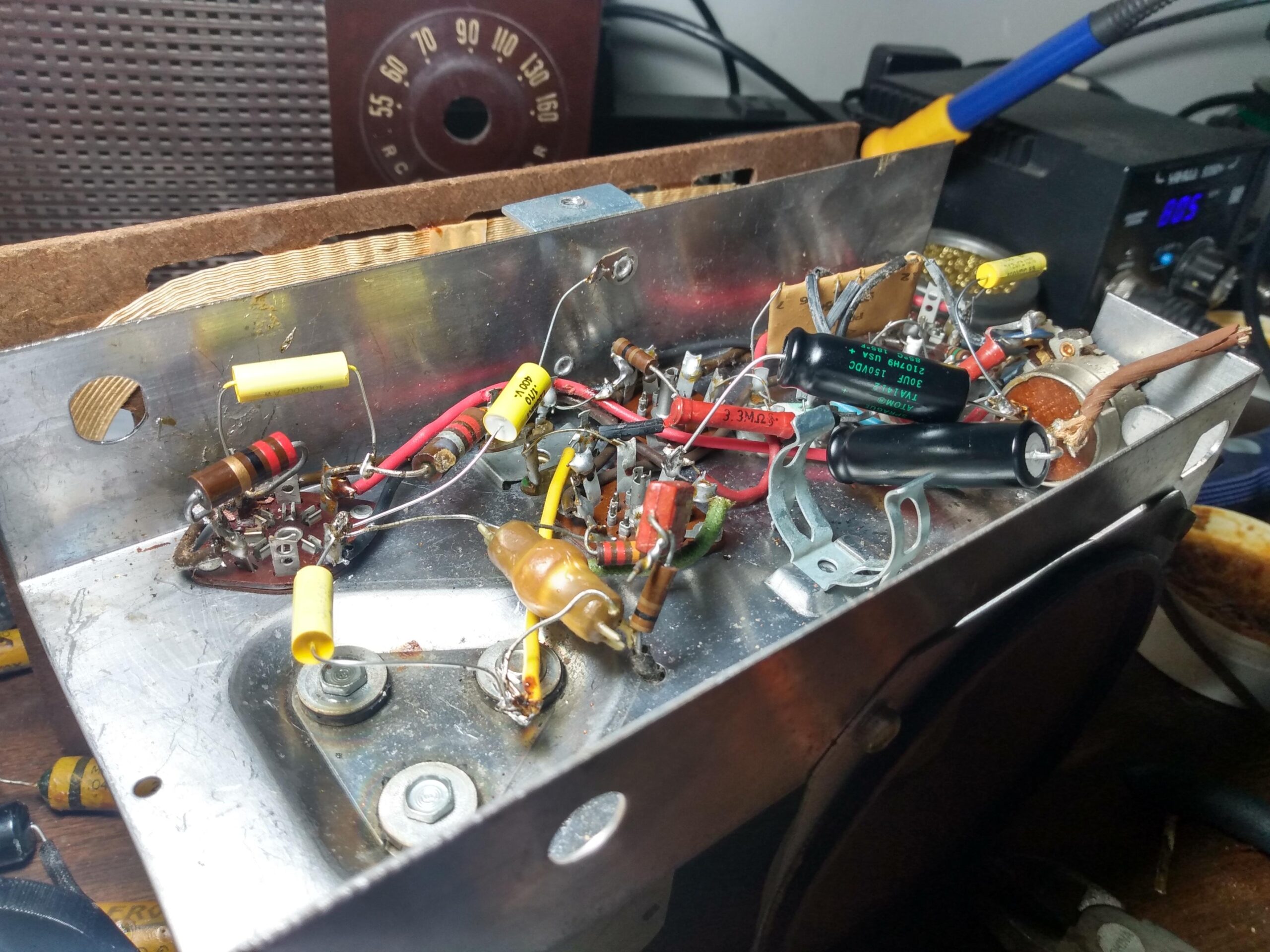
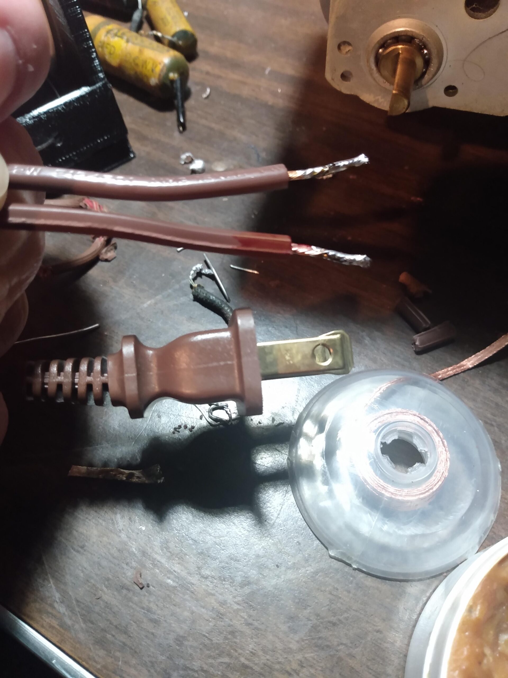
Wiring the electrolytic capacitors wasn’t eventful, they went in as expected with just enough room to bend them into compliance without shorting to the chassis. The last step was to add a new power cord. I salvaged a polarized plug and twinlead power cable from an old unused extension cord that matched the original brown. I reused the strain relief grommet that held the original power cable. The positive connection on the new power cord went to the appropriate terminal on the on/off/volume switch, and neutral to the terminal on the tube socket pin that the resistor was attached to in the first step of this restoration.
Electrolytics removedPolarized cable tinned~Fin~
All done! I rushed to slide the chassis back into the body of the radio, applied knobs to their respective potentiometer shafts, inserted the one retaining screw, and plugged the radio into the variac. After about 15 seconds (tube warmup time) and at around 110v AC, I heard things: https://imgur.com/PDXPEBa
I don’t consider this a full restoration, but I do consider this stage of this project to be complete. There is still a buzz across the entire AM band that I want to address, and I’d like to clean up the paint on the tuning knob. Some takeaways:
There are plenty of schematics available online for antique radios, but I wasn’t able to find one for this specific model, at least not one that was in a resolution that I could read. I’ll keep searching before I do any more work on this, because I think it will be necessary to resolve the buzzing.
Paper capacitors removed all tested within ~20% of spec, but the large electrolytic was >30% so it definitely needed replacement. Great after 70 years, but they needed to be replaced. I’ll keep them in a box for science experiments.
I learned a little about old AM radios and I’m ready to apply this to the next project (already acquired).
This certainly wasn’t a comprehensive restoration, but an old radio works again and that’s enough for now. If anybody has a readable schematic for an RCA Victor Model 3-X-521, please let me know.
For the last three years I have been driving around with the display for my TYT TH-7800 mobile radio on an articulating arm, and the main body of the radio under the driver’s seat. This worked well enough, but I found myself running the radio at full volume all the time, and while driving I was often unable to hear stations with weaker audio. I would have to concentrate on listening instead of driving, which isn’t ideal. I put up with this for entirely too long. Then in November of 2022 I swapped the TYT for an Icom IC-2730A. There were some other changes that came along with this that I’ll document later, but at this point I decided that something had to be done about the audio situation.
I picked up a nasty habit in 2022 of amassing radio gear by buying entire stations at once, and it was during one of these purchases I had acquired a Roadmaster external speaker. I am recklessly frugal, so I decided that it was better to use a speaker I already owned than to buy something else. It even came with a mounting bracket!
I had a few mounting options for the speaker. I could mount it under the front of the driver’s seat, but this was clearly a stupid idea because that maintains the exact problem I’m trying to solve. I could mount it under the dash on the driver’s side, but I felt this would get in the way. I have existing gripes with controls being low on the dash on the driver’s side, because I often rotate the headlight control knob with my knee when getting out of the truck. I could mount it on the driver’s side of the center console, but I wasn’t comfortable drilling holes in my unaltered interior trim.
Mount failed successfully
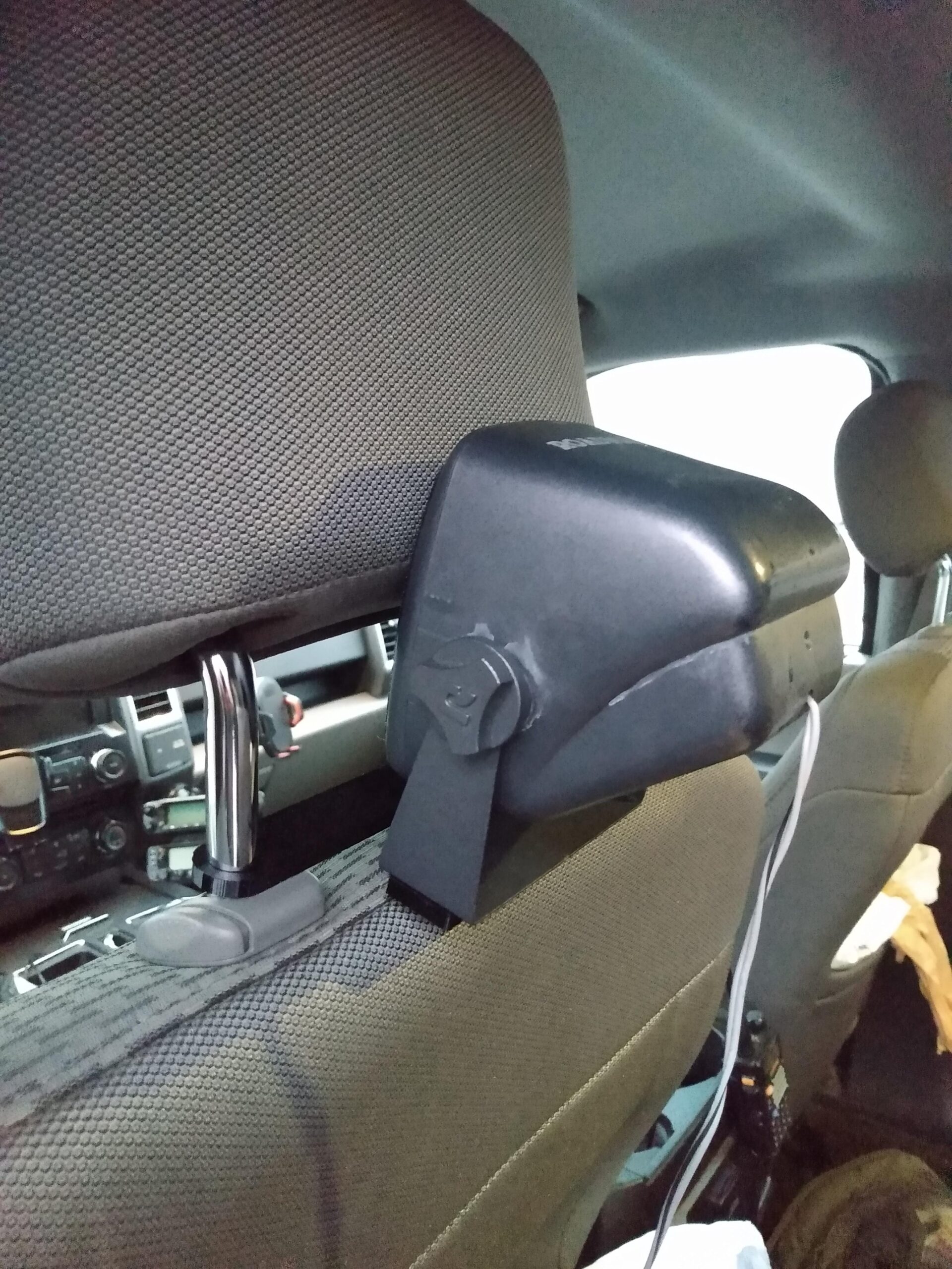
I recalled a time when I borrowed an antenna launching device from Cliff AC3EU and he showed me his headrest speaker mount made out of PVC. It was a simple solution, it put the speaker as close to the ears as possible, and didn’t require any permanent modification to the interior. Then I reminded myself that I own a 3D printer, which is perfect for dumb radio nerd problems like “how do I mount a speaker where speakers usually aren’t mounted?” So I grabbed the passenger side front headrest from my truck and started measuring.
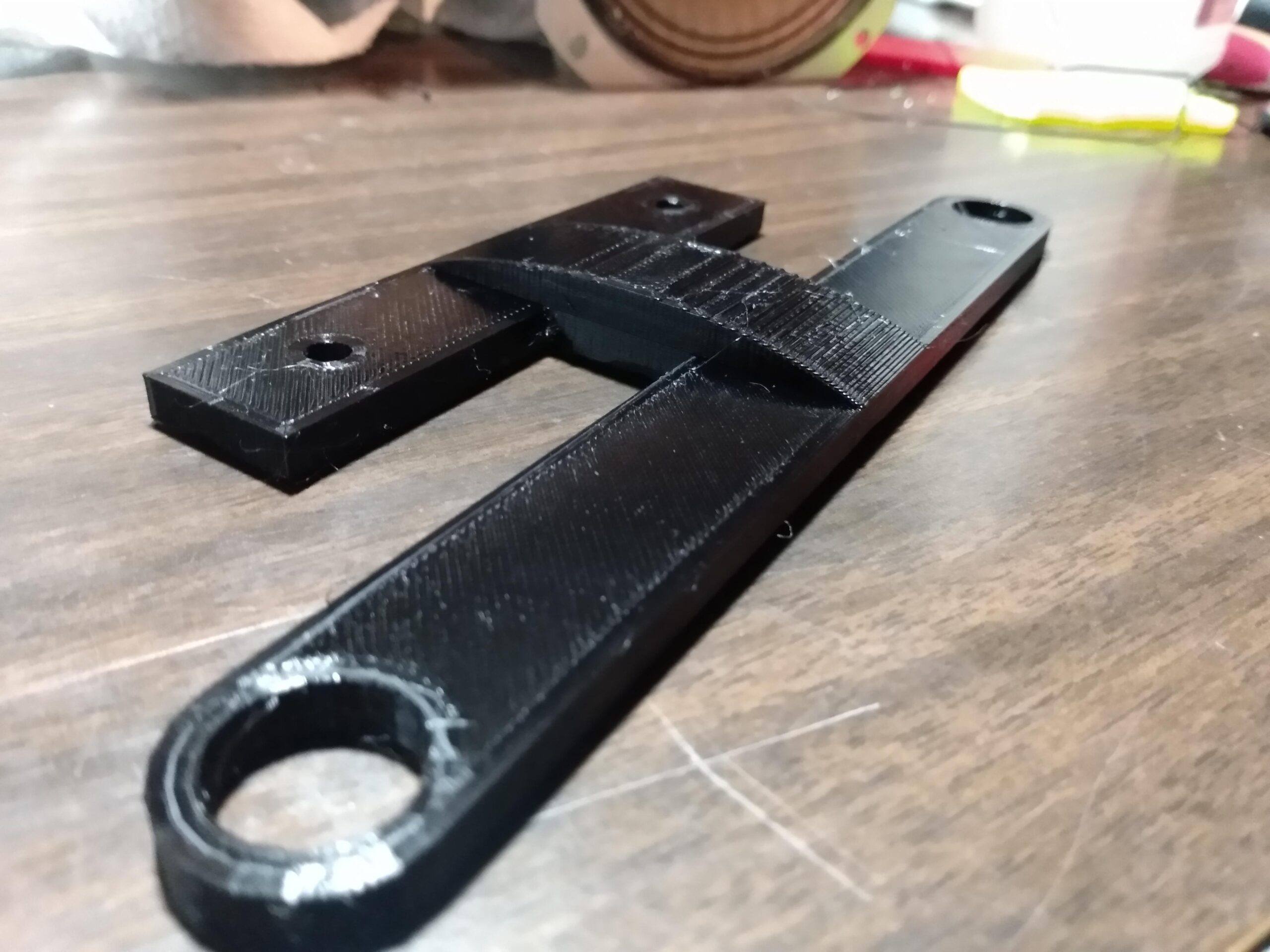
The two headrest posts are 150mm apart on-center, and each one is 13mm thick. The holes in the mounting bracket for the Roadmaster speaker were 69.69mm (nice) apart on-center. I designed a very simple 3mm thick mounting bracket in Tinkercad, which I then printed with black PETG. My very limited experience designing things gave me the wisdom to understand that it wouldn’t be the final version. Which was good, because the first mount broke immediately under the weight of the speaker.
There were other issues with this version of the mount. The posts on the headrest were 13mm thick, but 3D printing and object with a hole 13mm across often means that the hole in the finished print is slightly narrower. This is due to the elephant’s foot effect on the base layer, compression of the extruded filament on subsequent layers, sunspot activity, horizontal vs. vertical polarization, and date of your last Logbook of the World upload. So the holes for the headrest were slightly too small. I increased the size of the headrest holes on the model to 14mm for some additional wiggle room.
I also designed it with the holes slightly too close on the speaker mount side. My measurement of 69.69mm (nice) was correct, but I’m barely able to use Tinkercad so I screwed up the model. I moved the speaker mounting holes apart by about 2mm. In order to strengthen the mount to withstand the weight of the speaker, I increased the mount thickness to 5mm and added an arch to the bottom of the mount to provide strength under compression from speaker weight.
Headrest speaker mount V2 was expected to take about 4.5 hours to print, so I made sure the base layer adhered to the print bed and then found something else to do. When I sobered up, the print was done and it was ready for test fit. The mount printed upside-down, so the reinforcing arch appears on the top in the photo.
Mount V2Front viewBackseat view
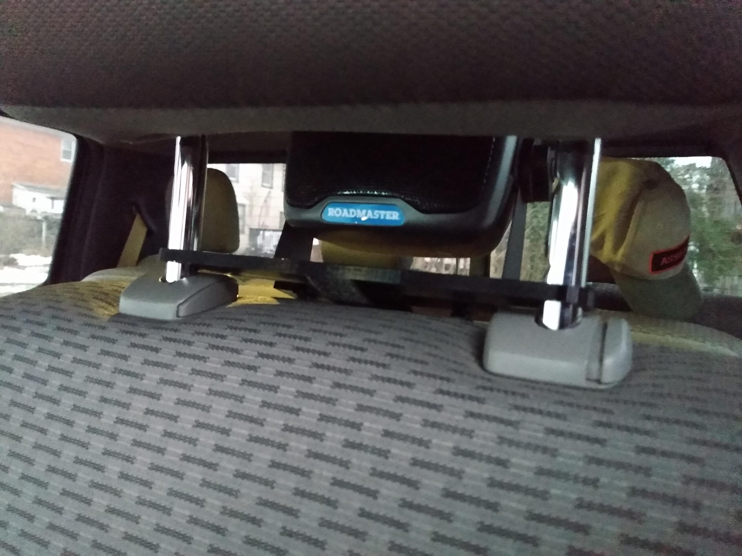
In Mount V2, the headrest post holes were big enough to slide effortlessly onto the posts, and the speaker mounting holes lined up with the holes in the mounting bracket. I used zip ties to mount the speaker to the mount because I’m tired of burning $2 worth of gas to go to the hardware store and buy $0.04 worth of nuts and bolts to mount radio project stuff.
The practical results: The speaker is mounted directly behind my head. I don’t need to crank the volume to hear quiet stations. I don’t need to crank the volume to hear ANY stations. Everything received sounds like it’s coming from inside my head. I can keep the volume low and still hear transmissions clearly, and radio chatter doesn’t irritate my passengers. And with the speaker so close, I get relatively good quality audio that would otherwise be lost amongst the regular cabin noise at highway speed.
STL file of the headrest mount is available upon request.
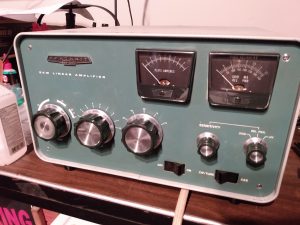
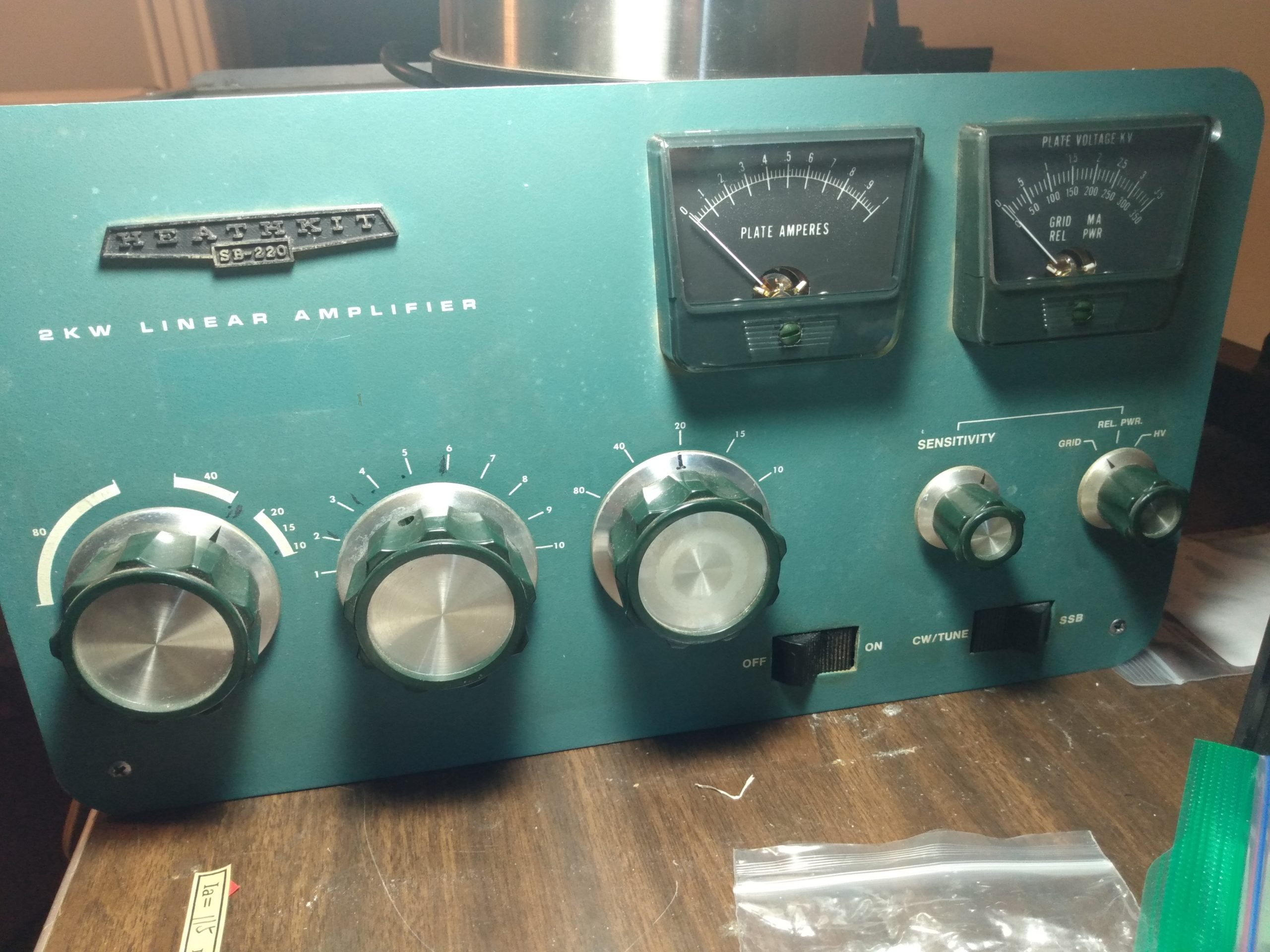
This is my Heathkit SB-220 amplifier. There are many like it, but this one is mine.
I wasn’t specifically looking for a new amplifier when I found this SB-220 on the QTH.com classifieds, but the price was worth the constituent parts of the amp on their own, never mind the two 3-500ZG tubes, so I knew it would be a worthwhile project no matter what shape it was in. After spending so much time attempting to repair my AL-80A I had developed an affinity for older tube gear, and I was intrigued and allured by the prospect of owning a tube amplifier that would get me over 1KW of RF and close to legal limit power.
I asked a few questions, and got a few answers. The seller had purchased it from a SK estate (couldn’t remember who) and didn’t know if anything had been done to it, but it did power on. After working out details with the seller and giving him a chance to test the amp, it was time to pick it up. With a promise to buy her dinner, the wife and I left town around 3PM on a Friday afternoon and started the 2 hour drive to Wilkes-Barre PA to pick it up.
Dinner was at Breaker Brewing Company in Wilkes-Barre, we got loaded nachos and paninis. Would recommend.
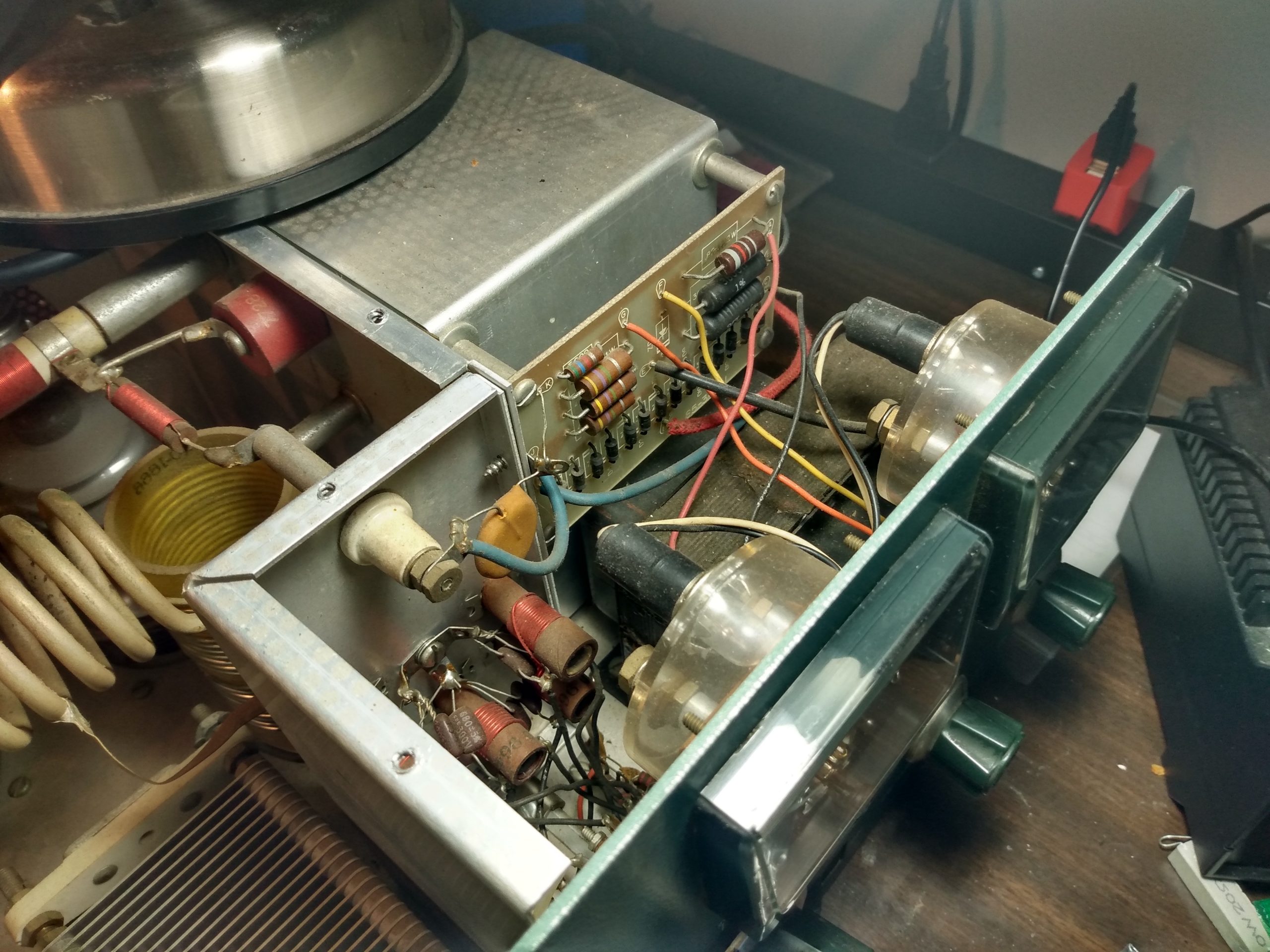
Upon return to the QTH, the SB-220 went straight to the bench. I didn’t even turn it on, because I wasn’t interested in how it operated now – I would be changing things. I wanted to know what I was dealing with first.
A note on disassembly of the SB220: It is time consuming. The entire chassis lives within a single piece outer shell, and removing the chassis requires orienting the amplifier in several different positions. This amplifier is HEAVY. Once the chassis is removed from this outer shell, the high voltage area of the amp is still sealed behind a panel with at least 12 screws. On my amplifier these screws had no less than 3 different heads. This also foreshadows the re-assembly of the SB-220…
“It appears to be mostly original”
The following images are the SB-220 out of its shell, before I made any changes. The meters and knobs appeared to be original. The knobs showed some wear, but this builds character so they won’t be replaced.
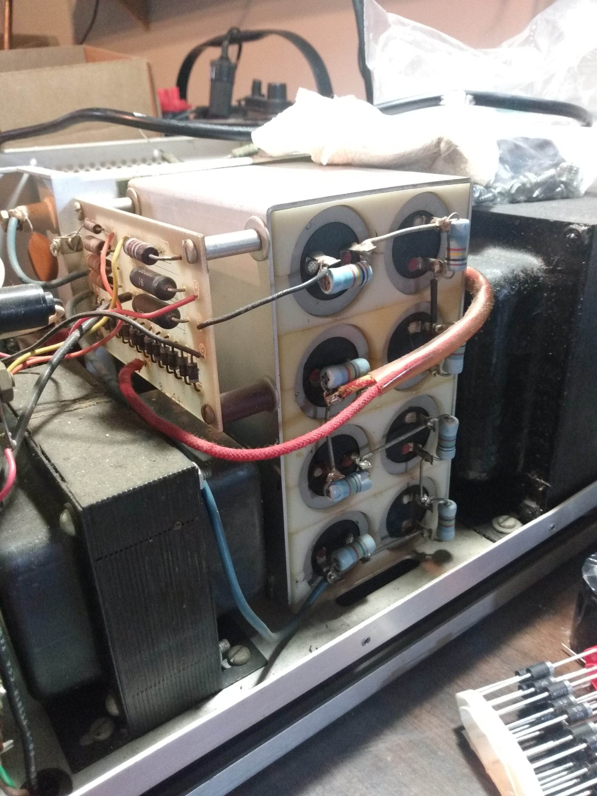
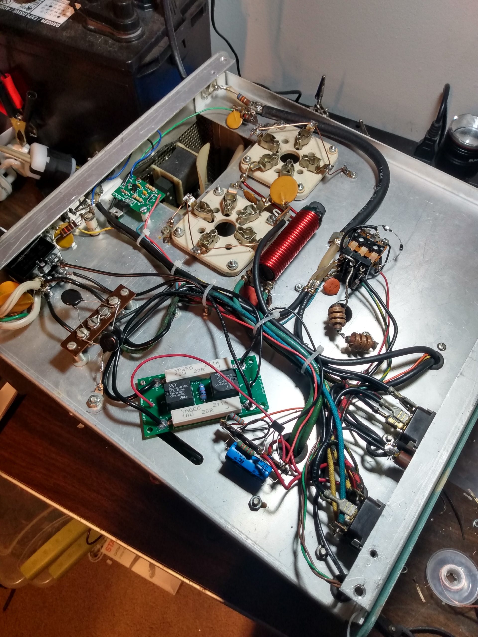
SB-220 Removed from outer shellSB-220 filter capacitor blockPower board, meters, input coilsSB-220 as I received it
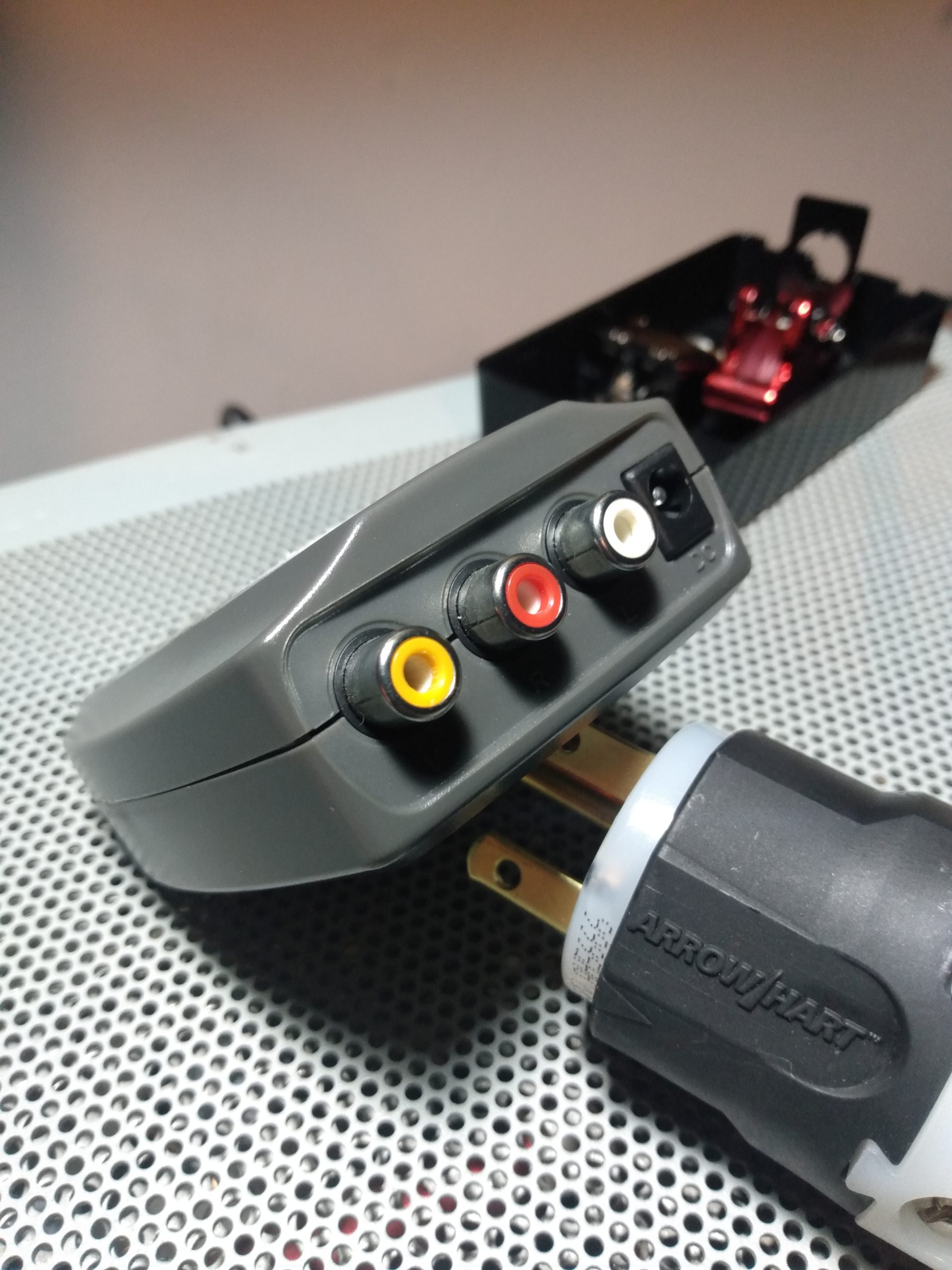
The stock power cable had been extended, presumably because the OM who had last used it needed a few more feet to get to his 240v outlet. It was ugly, but spliced correctly and appeared to be fully functional. This extension would be removed and a new 240v 6-15R plug put in its place. I did not need the extra wire length because my 240v outlet is directly next to my radio rack.
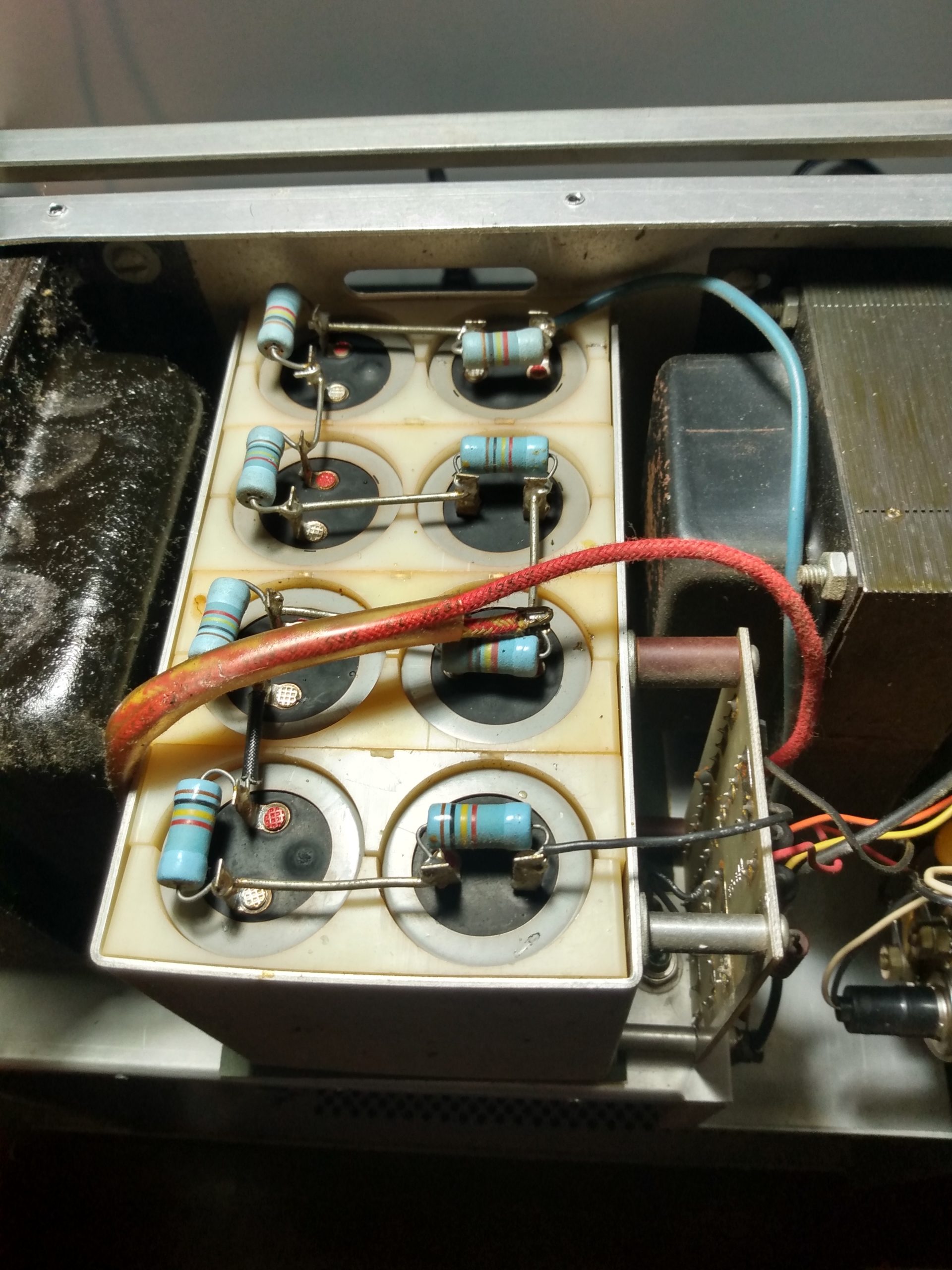
The filter capacitor bank contained the original plastic spacers, but the Nichicon capacitors and resistors did not appear to be original. I tested them and they all seemed to be within spec. Regardless, their age could not be confirmed so they would be replaced.
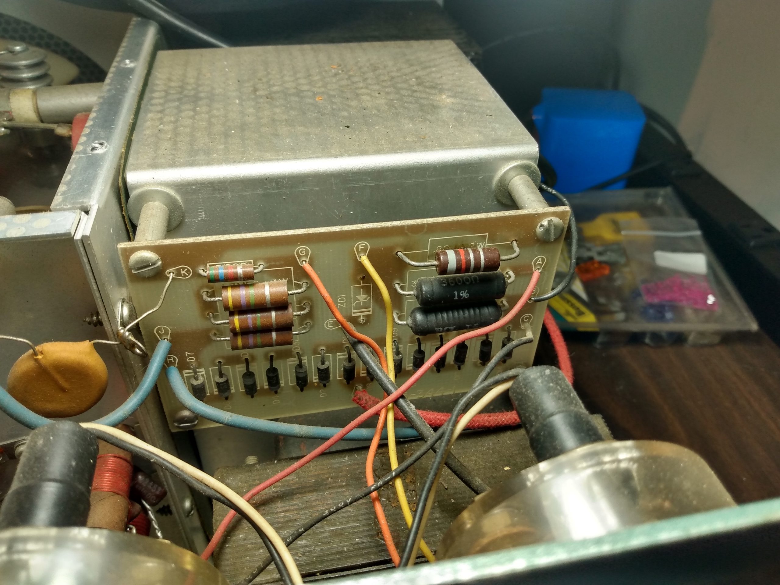
The rectifier/metering board and all components were original. There didn’t seem to be any issues with the board, and the meters did not appear to be modified with protection diodes. At this point I considered praying that the meters still worked. I wouldn’t know until I turned the amp on for the first time.
The input coils were in good shape, but the 20m coil did not look original. Not sure if it was replaced or if it was just built with different wire.
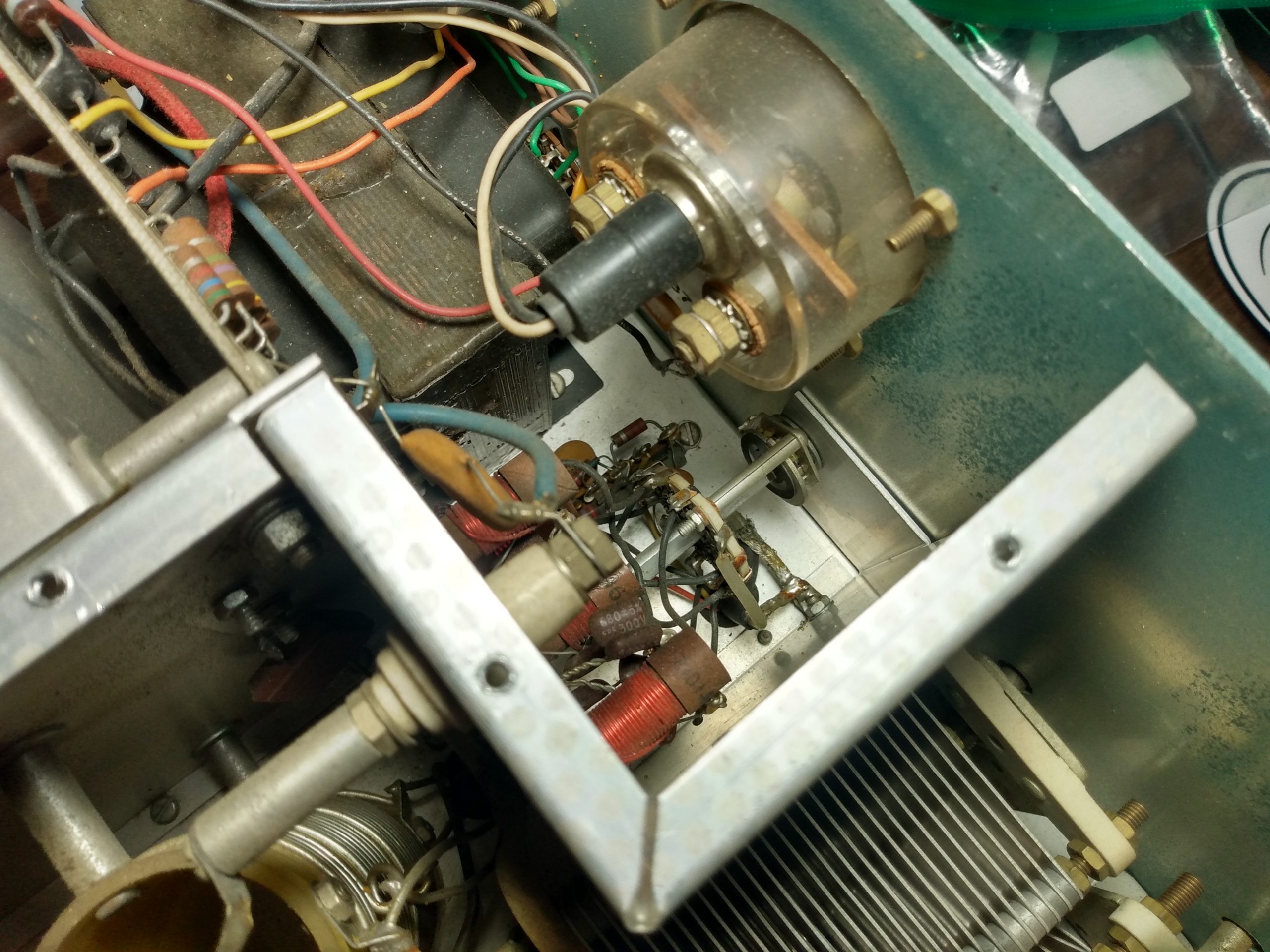
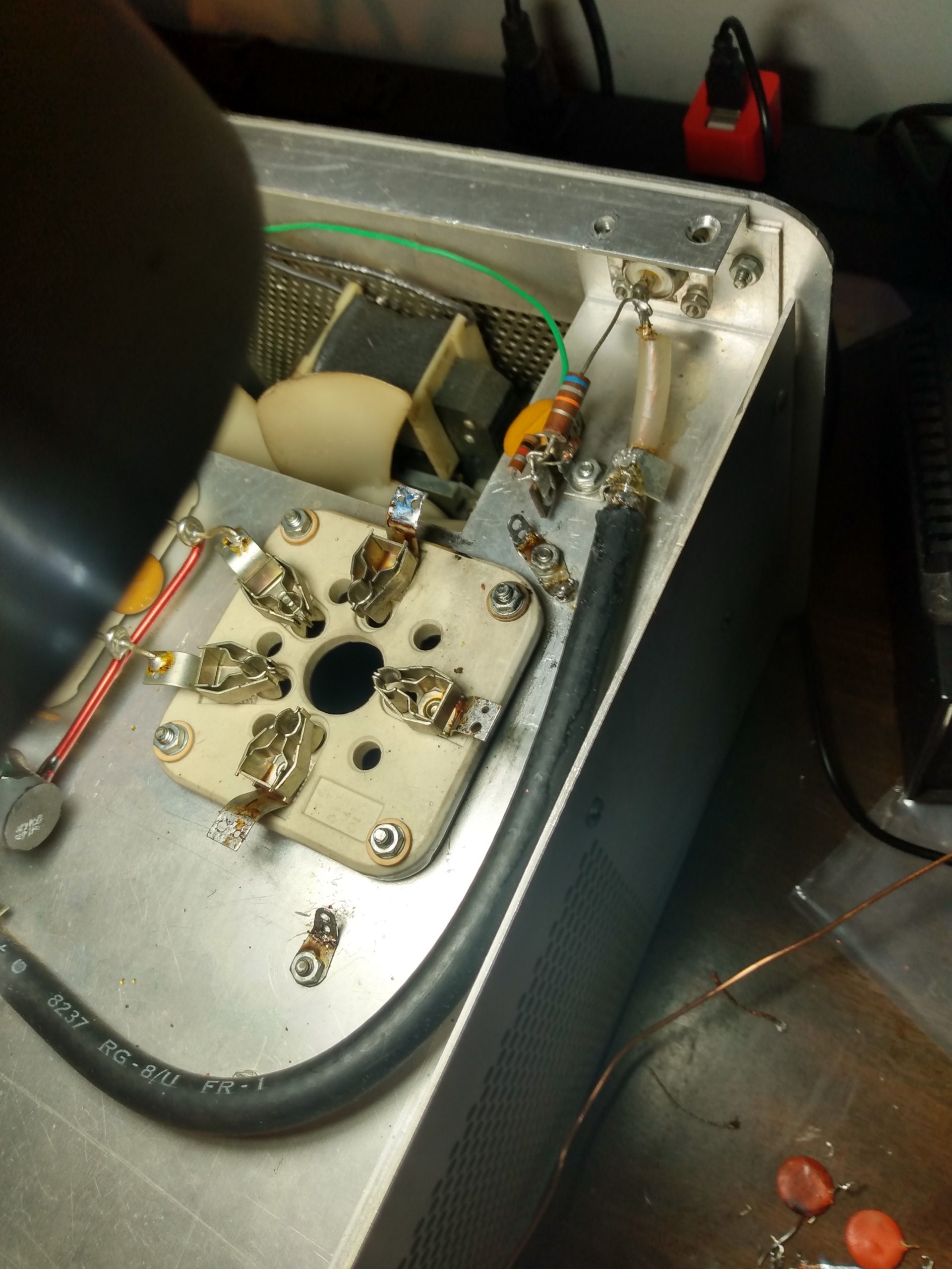
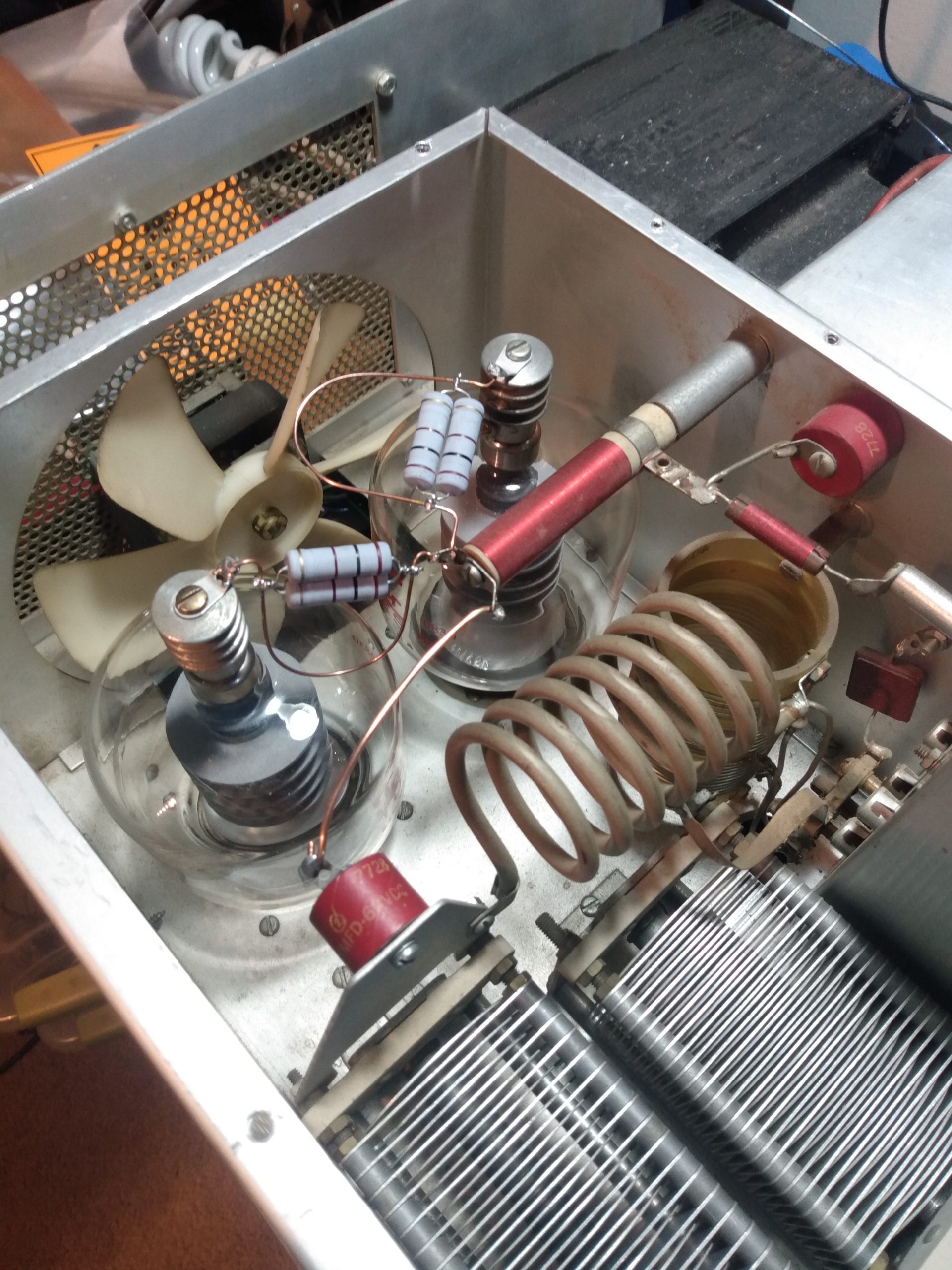
At first glance, or to the untrained eye, everything looks fine in the “tube chamber.” It wasn’t. There was a uniform amount of dust on all components, but this just meant that the amplifier hadn’t been messed with much lately. I erroneously took this as the amp being “unmolested.” I’ll go into more depth with this later.
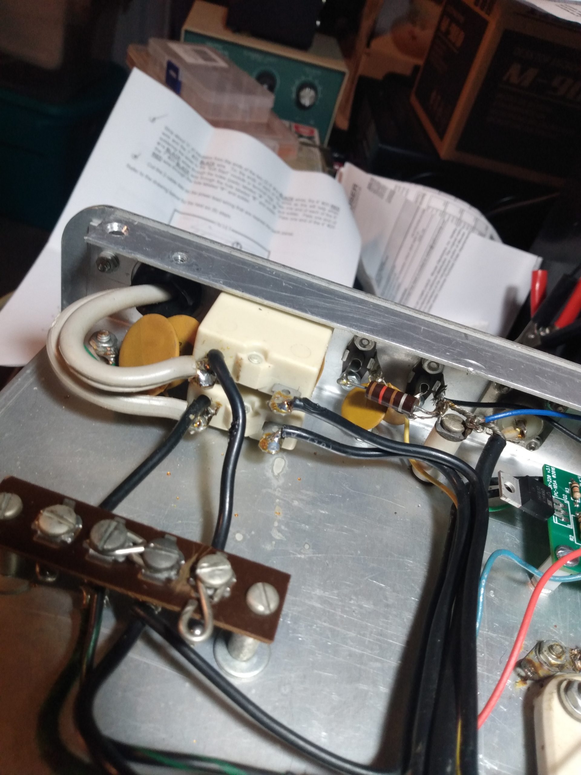
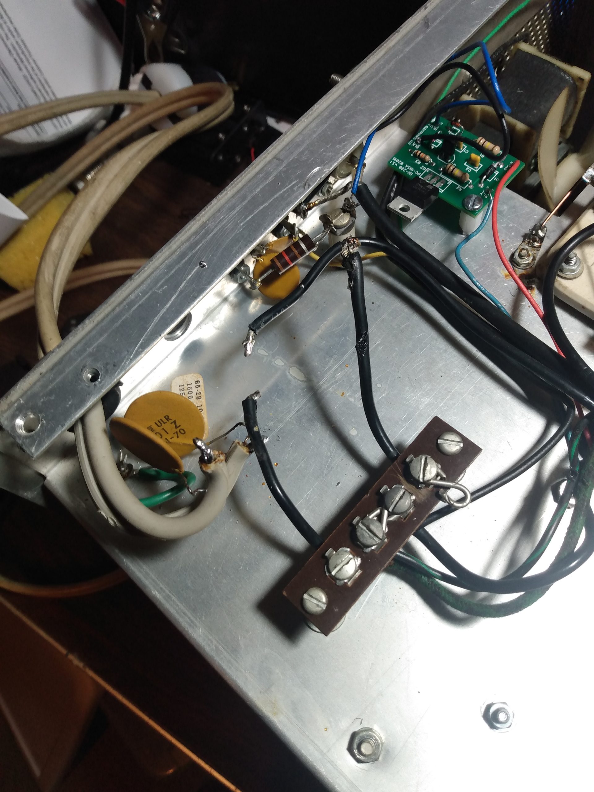
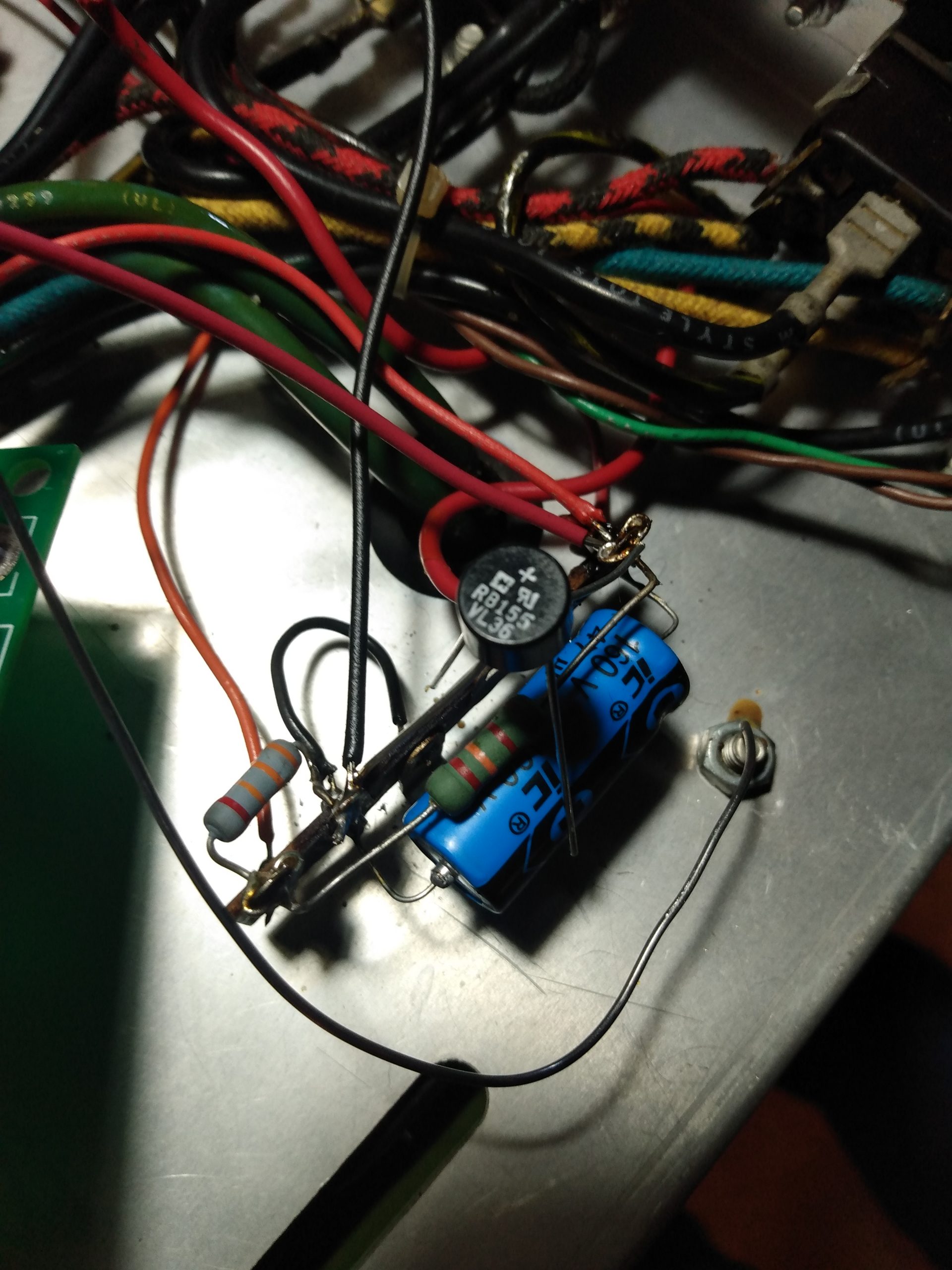
The guts of the SB-220 appeared fine at first. Digging in, a few things jumped out at me. There is a capacitor connected to a terminal leading to the 120v transformer that appeared to be replaced, and physically leaking. This capacitor is known to blow in case of tube flashover, so I marked it for replacement. This lead me to the grid connections on the tube sockets, which were not grounded. Grounding the grids on the SB-220 is considered best practice (explained later), so I added this to the todo list.
The fan was original, and it spun freely, which I’ve been told is unusual for this vintage. I decided to keep it, for now. Both transformers also appeared original and in good shape.
Original power boardLeaky capacitorInput coilsBandswitch, input coils, plate meterPower board and filter capacitor bankPower cable extension
Preparations
Now that I had some idea of what I was dealing with, I laid out my objectives. I already had a working amplifier, an Ameritron AL-80A, that (after repairs) had proven itself pretty reliable loafing along at 500-600w. I like this amplifier and have no intention of selling it. But I wanted this SB-220 to be the new primary amplifier in my station, capable of running 1KW+ for extended periods of time on most bands, with all the modern upgrades that would extend its life for another 20+ years and allow it to be keyed by modern rigs.
The SB-220 came with a pair of Taylor 3-500ZG tubes, which are PRC reproductions of the venerable Eimac 3-500Z. I did not know what electrical state these tubes were in, but I didn’t want to replace them if I didn’t have to, so I removed them, cleaned them, and packaged them carefully for long term storage (note: tubes can be cleaned with isopropyl alcohol, but the alcohol will remove the logos). New matched 3-500ZG tubes run about $500, so I’d forego this cost if the tubes ended up being good.
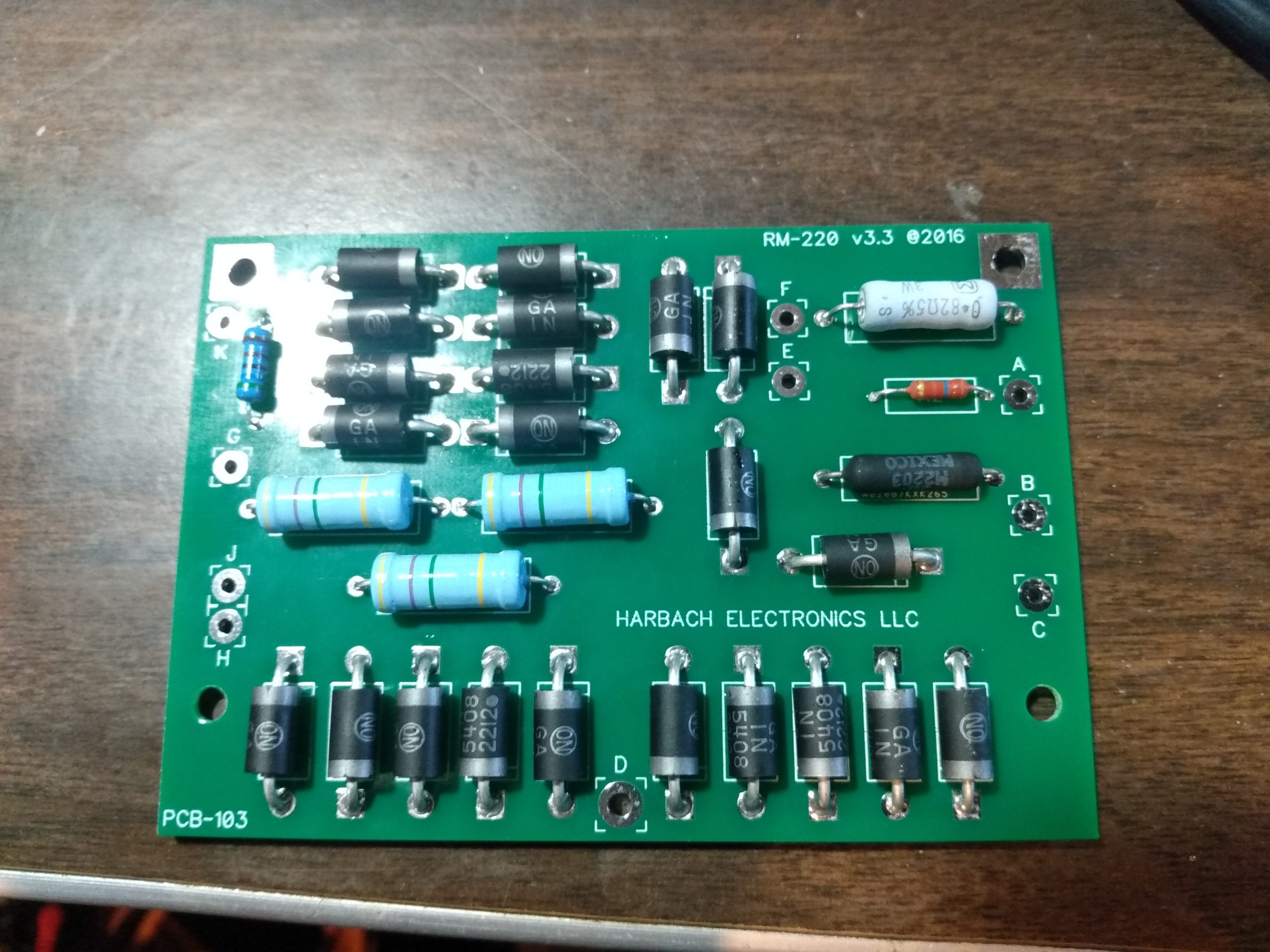
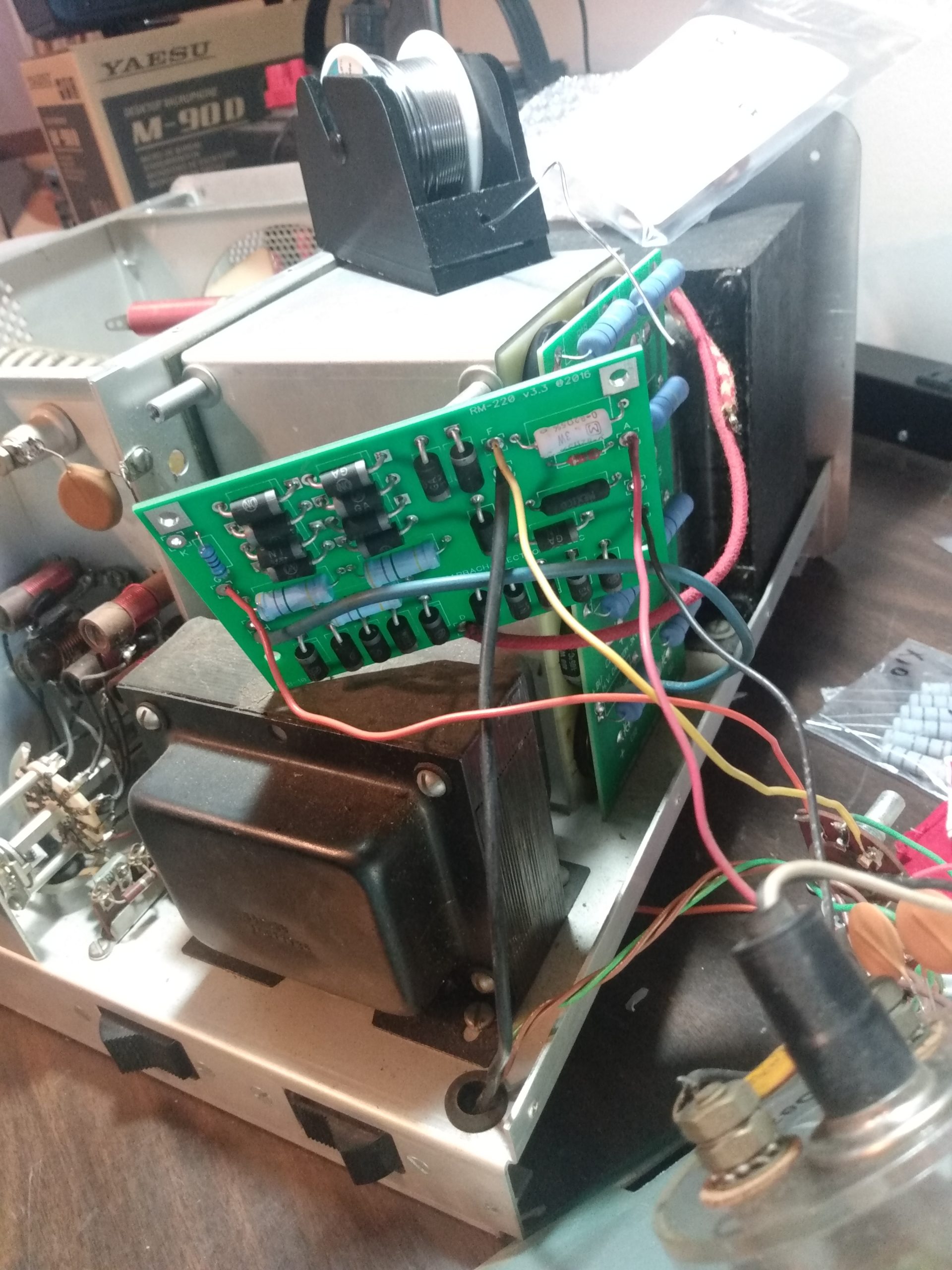
Harbach Electronics makes several replacement board kits for the SB-220, and I opted to use all of them for this project:
The RM-220 rectifier/meter board replaces the stock power board and is an improved design that also includes meter protection. As a result, the well-documented meter protection mod for the SB-220 that I planned on doing would not be required.
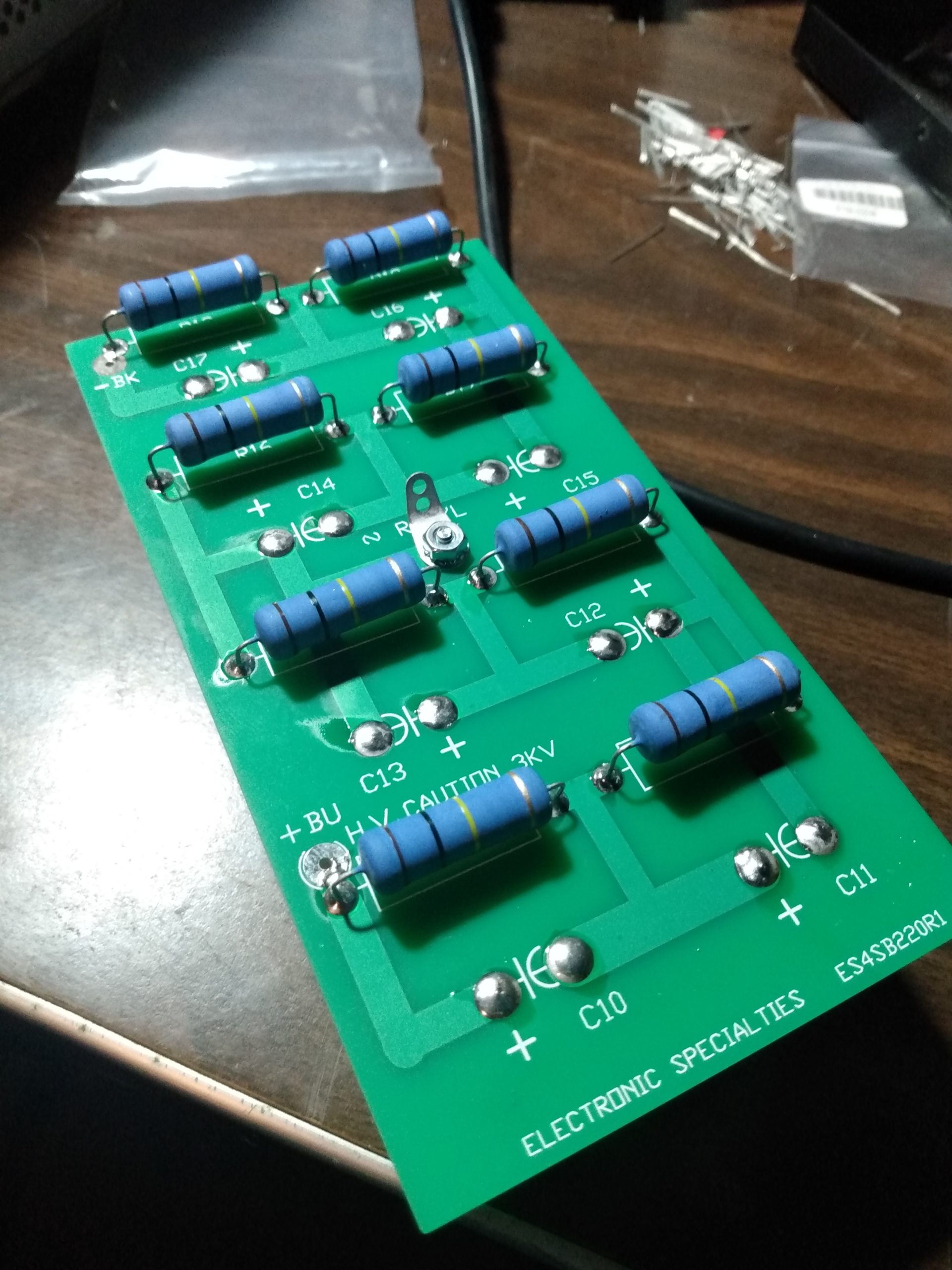
The ES4SB220 filter board replaces the existing filtering capacitors and resistors and fits into the stock plastic spacers. The caps and resistors are rated higher than necessary for additional overhead and we are told they run cooler than stock, which is a good thing in an enclosure with tubes that generates a lot of heat.
The 3-500Z is an “instant-on” tube, so the SS-221-240 soft-start board wasn’t 100% necessary. But inrush current can also negatively affect hard to find (and expensive) components such as Heathkit on/off and band switches, so it’s well worth the $35 to install this board. Quoting Harbach Electronics: “The SS-221 limits inrush current during amplifier start-up by placing a small resistive load in series with the AC mains. The load is switched out of the circuit by the relays a few milliseconds later.”
Back in the 70s when this amplifier was designed, it was keyed by a boat anchor radio via 120VDC. Trying to key this amplifier with a modern transceiver would damage the transceiver’s keying circuit, and possibly other parts of the radio. The SK-220 is a soft-key interface for the SB-220, allowing the amplifier transmit relay to be engaged with under 1VDC @ 1.5mA. This is a necessity.
SB-220 Restoration
Before building the new boards and installing them, there were a few things that needed to be addressed.
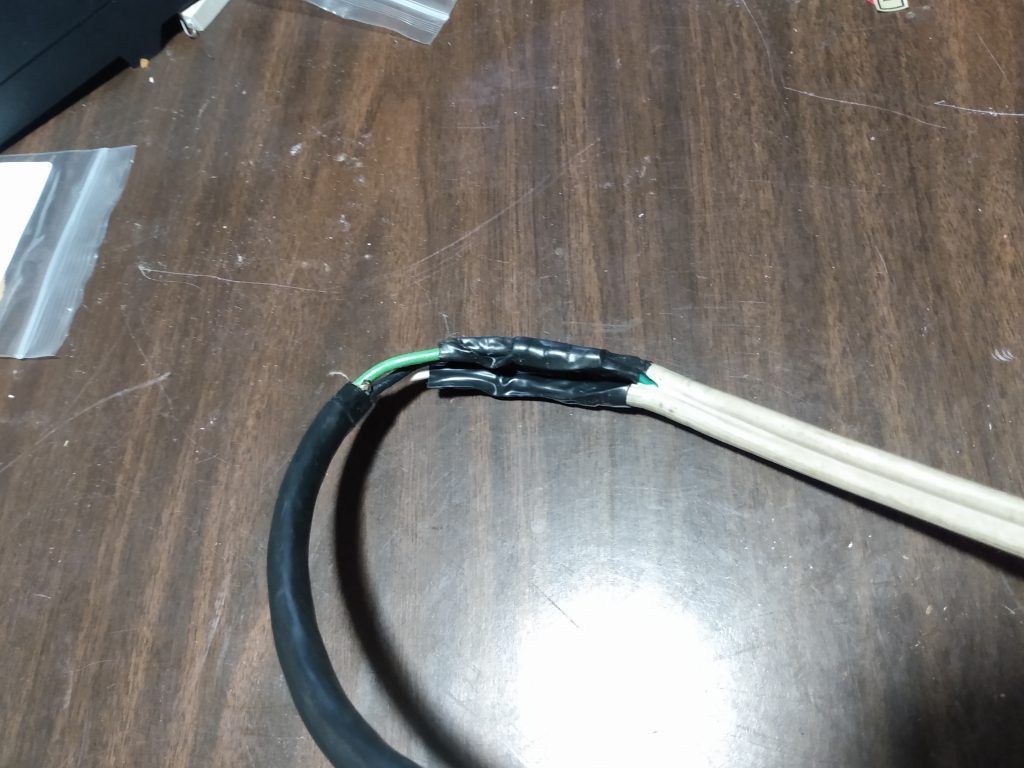
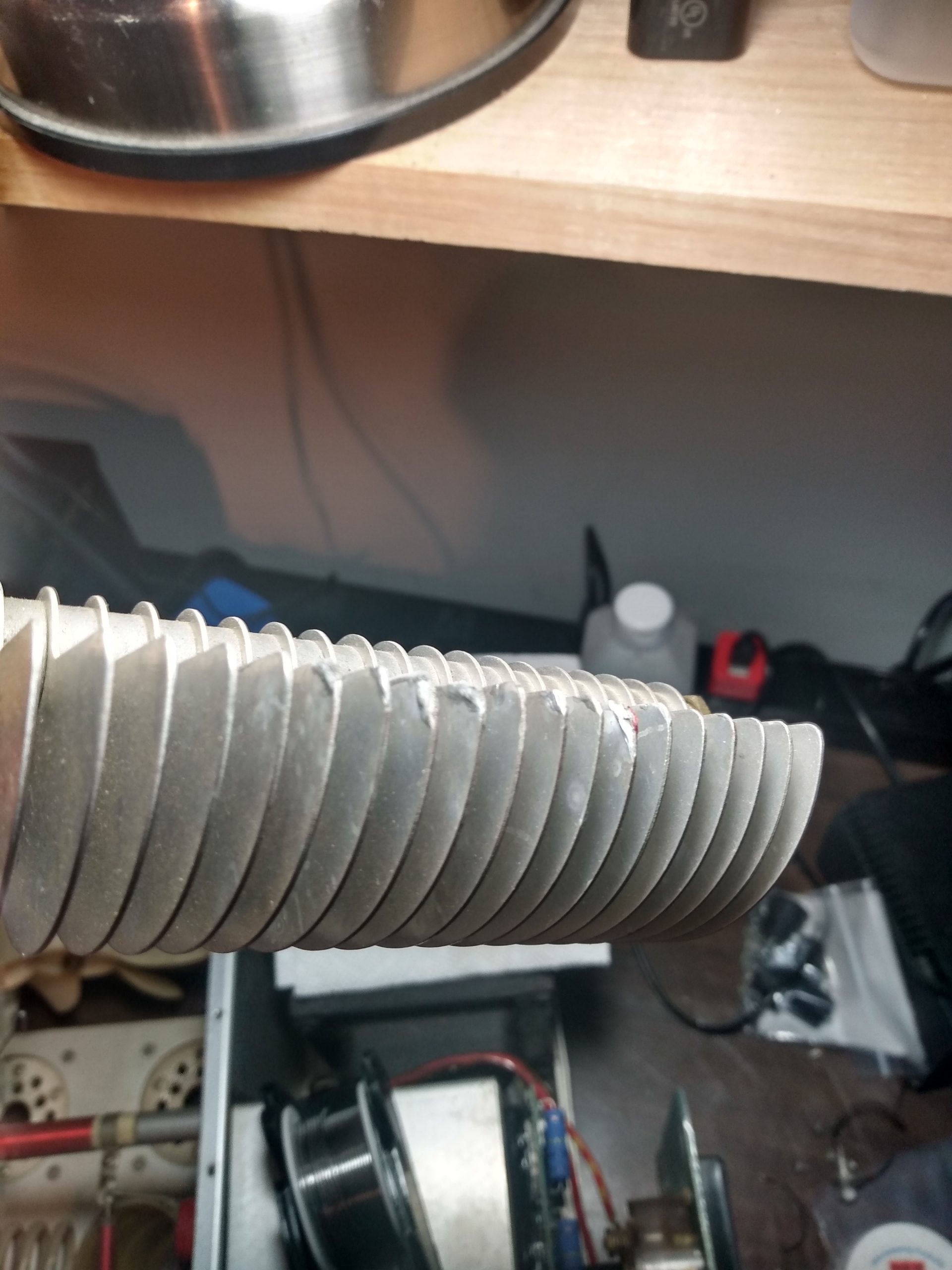
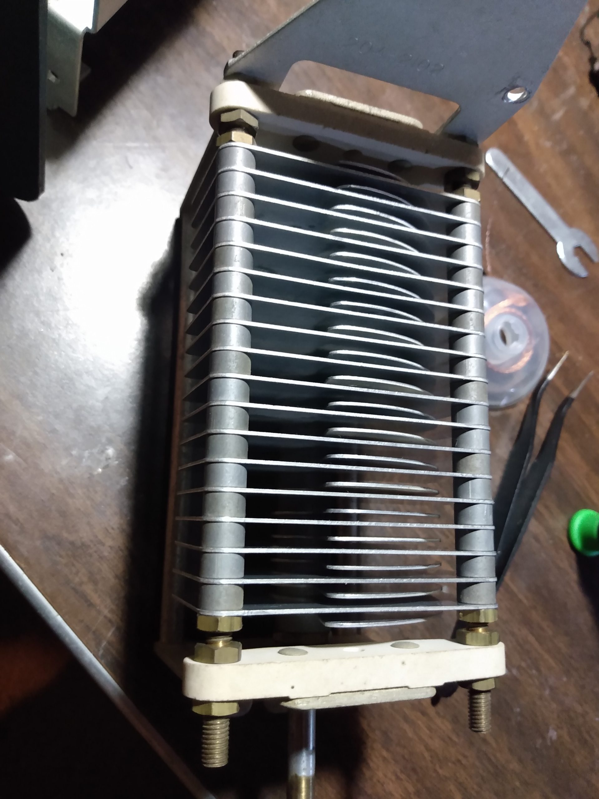
The plate tuning capacitor looked great at a glance. But closer inspection revealed that it had been arcing repeatedly, which had damaged the rotating blades. Only after removing the rotating blades from the capacitor did the extent of damage become apparent. I suspect that the capacitor arced once due to a bad tune, which deformed the tip of a blade, which changed the capacitance of the capacitor, changing the tuning, causing more arcing, repeating over and over again. Clearly it had been abused. It would have to be completely disassembled to be repaired.
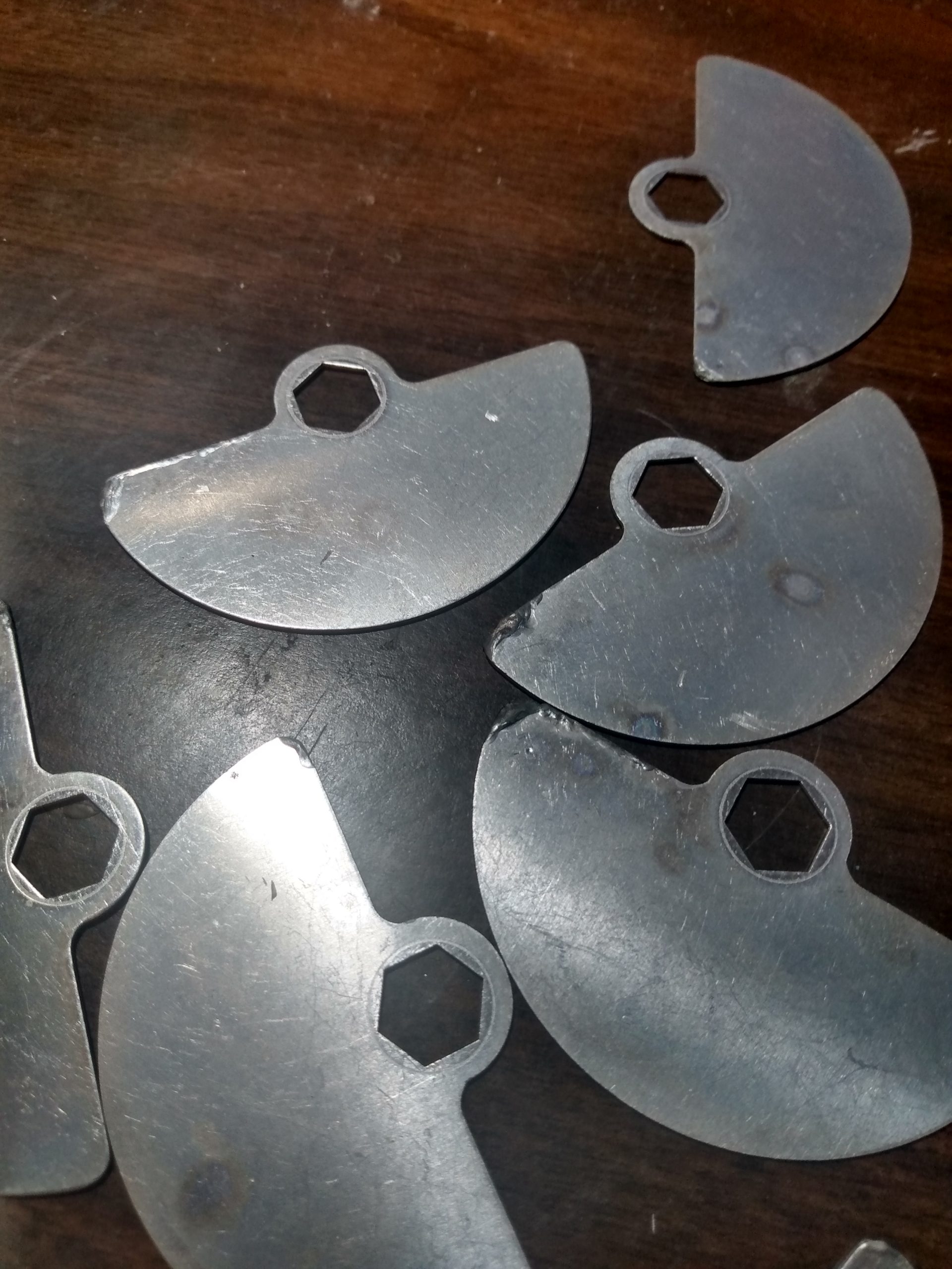
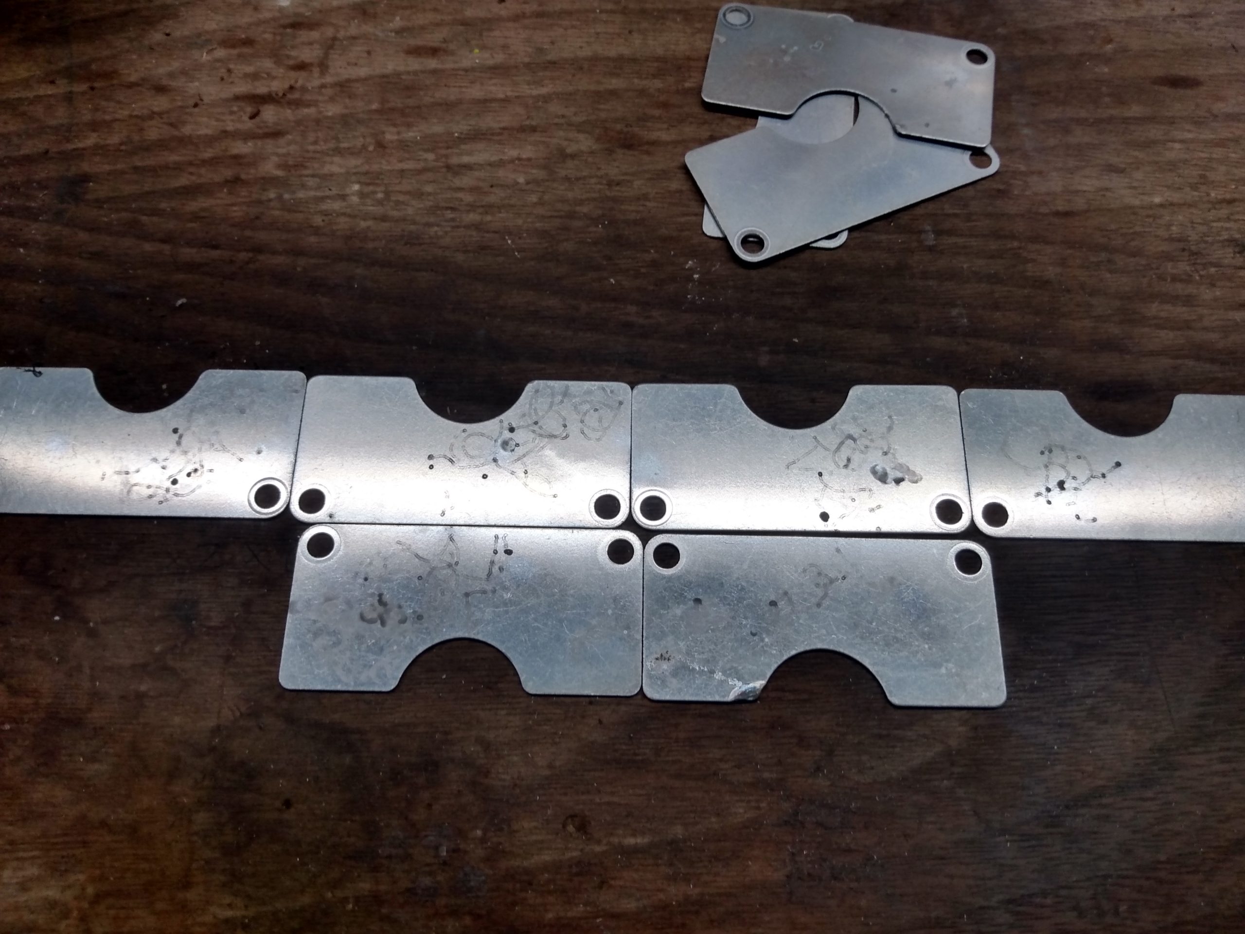
I removed the blades from the main assembly, and found that roughly half of them had been damaged. I believed it could be salvaged by sanding and polishing each of the blades. First I sanded the deformed part of each blade on a flat surface with 220 grit sandpaper. Once the blades were again flat, each was polished with 0000 steel wool. There was only minor loss of material on some of the tips of the blades. You wouldn’t know unless you knew what to look for. The important detail is that now all the blades are straight and uniform thickness so they should mesh evenly.
I also disassembled the fixed blade assembly of the capacitor and found some neat squiggly electriciy drawings, and some damage to a few blades. These were sanded and polished in a similar fashion, but the damage was minor in comparison to the rotating blades.
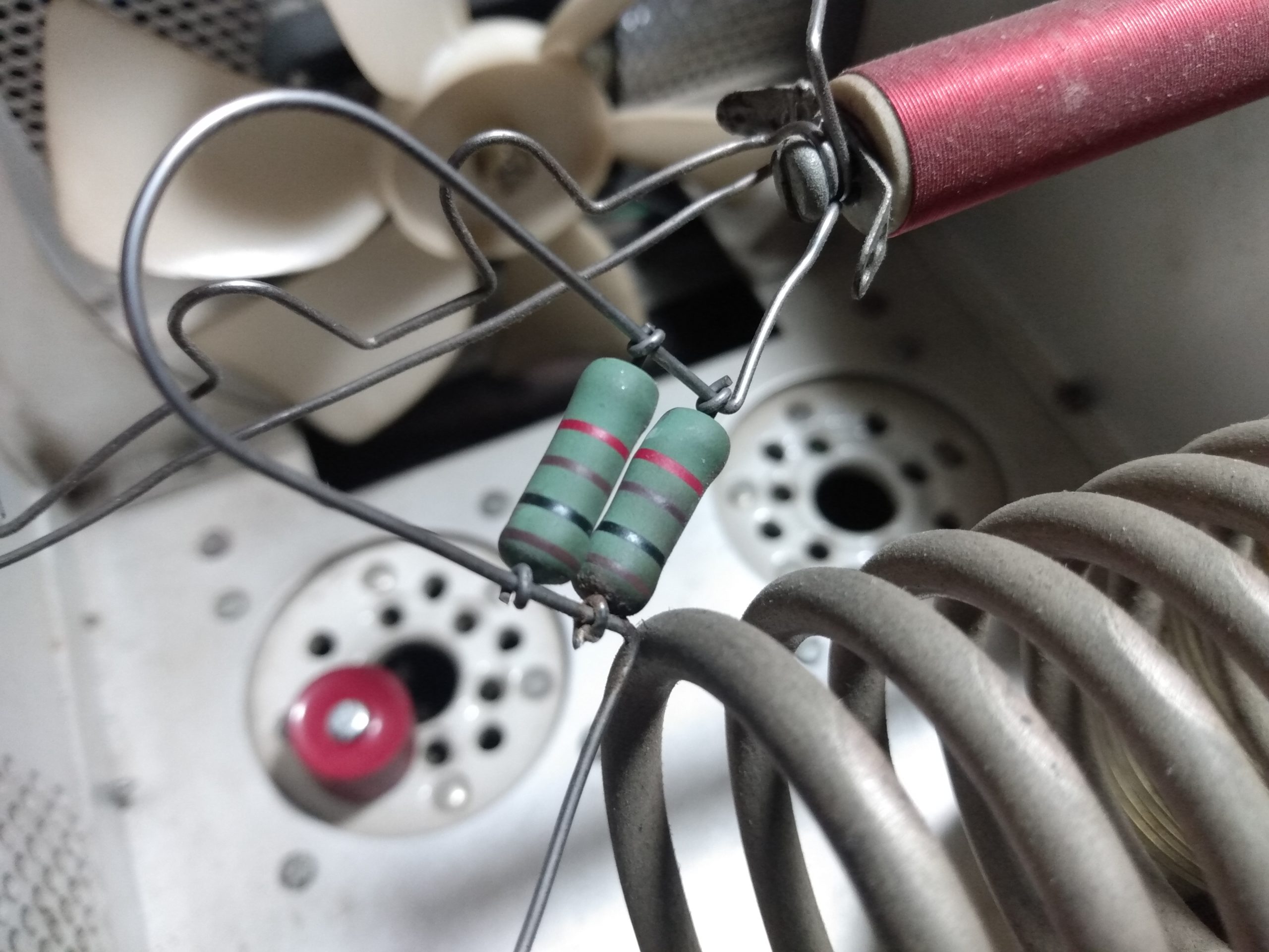
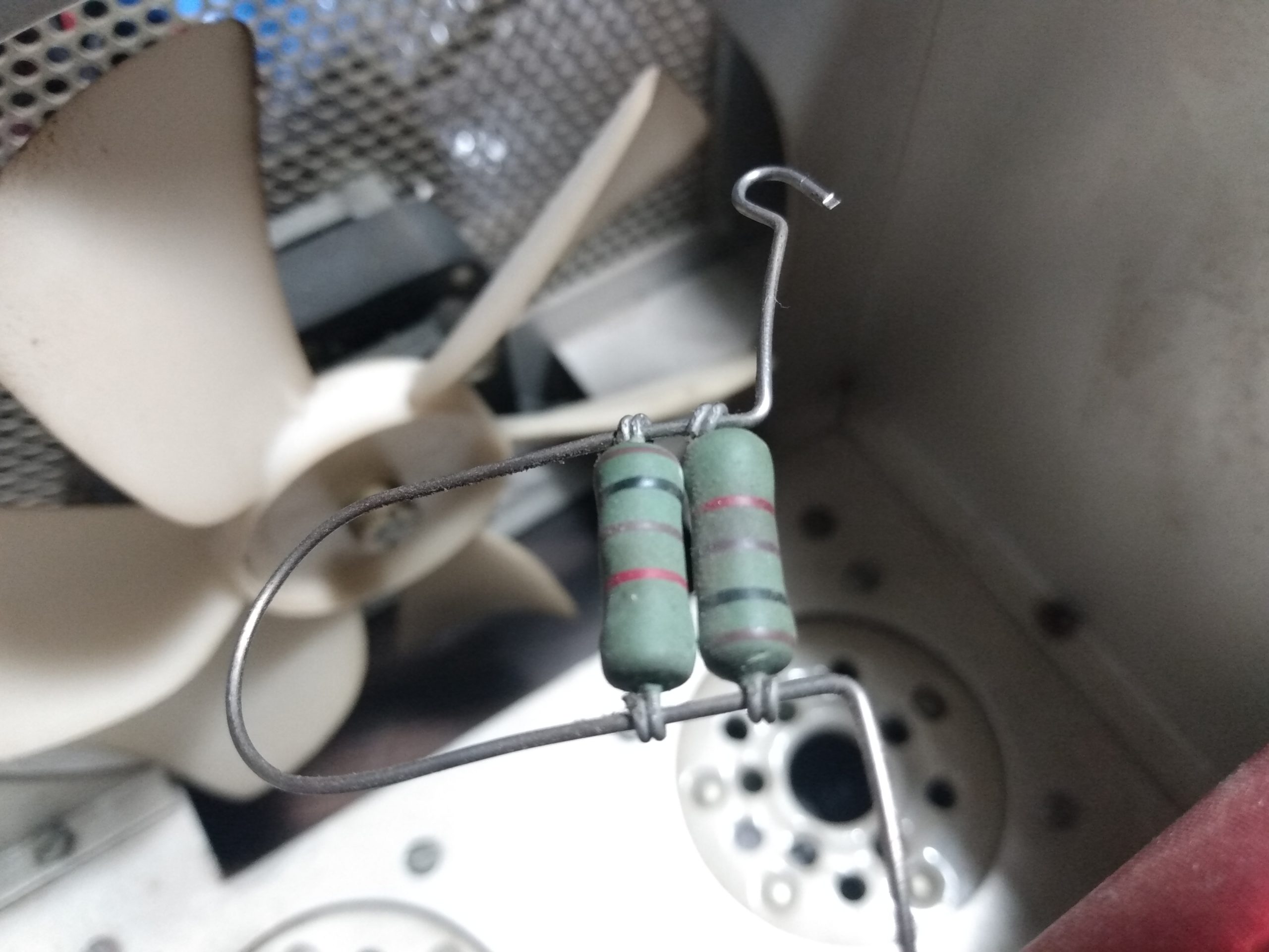
I knew enough about 3-500Z amplifiers to know that these parasitic suppressors were not original, which didn’t concern me. But the fact that these suppressors were not soldered DID concern me. The leads of the resistor were just wrapped around the bent wire, free to slide around. There was evidence of arcing on the side of at least one of these resistors. And the suppressors themselves were not soldered to the lugs on the coil (despite these lugs being present), instead they were wrapped around the screw and held in place by friction. These would have to be replaced.
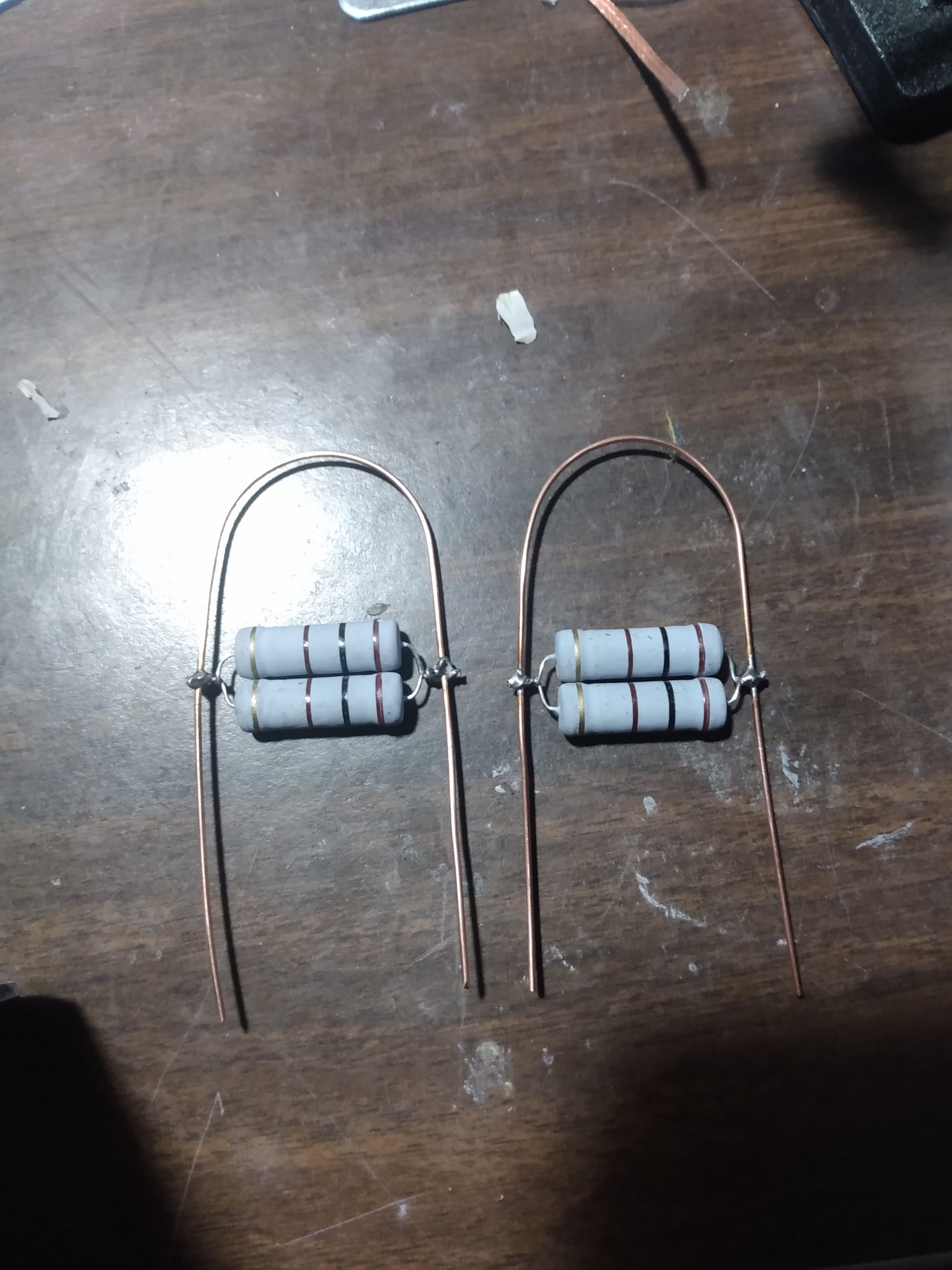
Poorly built parasitic suppressorAnother poorly built parasitic suppressorNew parasitic suppressors
I built new parasitic suppressors with 18 gauge copper wire and 100 ohm 5 watt resistors, making sure to solder the connections between resistors and wire. These would not be installed until the tubes were back in their sockets, so I set them aside.
It was time to remove the original power board and filter capacitor bank, which would both be replaced by the modern Harbach kits. The capacitor bank is held in place by bolts on the bottom of the amplifier, some of which are hard to get to due to existing wiring, so rather than remove the capacitor bank completely, I just loosened those bolts enough that I could cut the leads connecting the capacitors and remove them. I took great care to not damage the original plastic spacers that hold the capacitors in place, they would be reused with the new kit.
With the old capacitor bank removed, I took out the screws holding the faceplate to the front of the amplifier and swung it to the right of the case to begin removing the original power board. There were also some structural components removed to do this, those were set aside for eventual reassembly. During desoldering and removal of the power board, I noticed that one of the two capacitors on the meter lamp circuit had failed catastrophically. The capacitor had blown hard enough to leave a residue on the back of the faceplate. I’m not sure what could have caused this, and I crossed my fingers that it hadn’t caused damage that I couldn’t see. Parts were ordered, and both the blown capacitor and its original unscathed companion were replaced with new components.
Original power boardOriginal meter circuitryCapacitor bank removedBlown capacitor on meter lamp circuitNew capacitors installed
At this point I replaced that leaky capacitor attached to the 120v transformer. I had seen this capacitor referenced as one of the first components to release the magic smoke during a tube flashover, so I paid special attention to it. The fact that it had some discoloration around the negative terminal spoke to the possibility that it had experienced some abuse, so it seemed a smart move to replace it. While doing so, I managed to snap the attached diode in half, so that was replaced as well. This was a simple job, but I did not realize that I would be removing that diode during the install of the Harbach soft key board in the near future anyway.
Non-original capacitor (suspect)Leaky capacitorRemovedNew capacitor and diode ready for solder
With the problem areas of the SB-220 taken care of, it was time to focus my efforts on the upgrades and modifications necessary to modernize this amplifier.
SB-220 Upgrades and Modifications
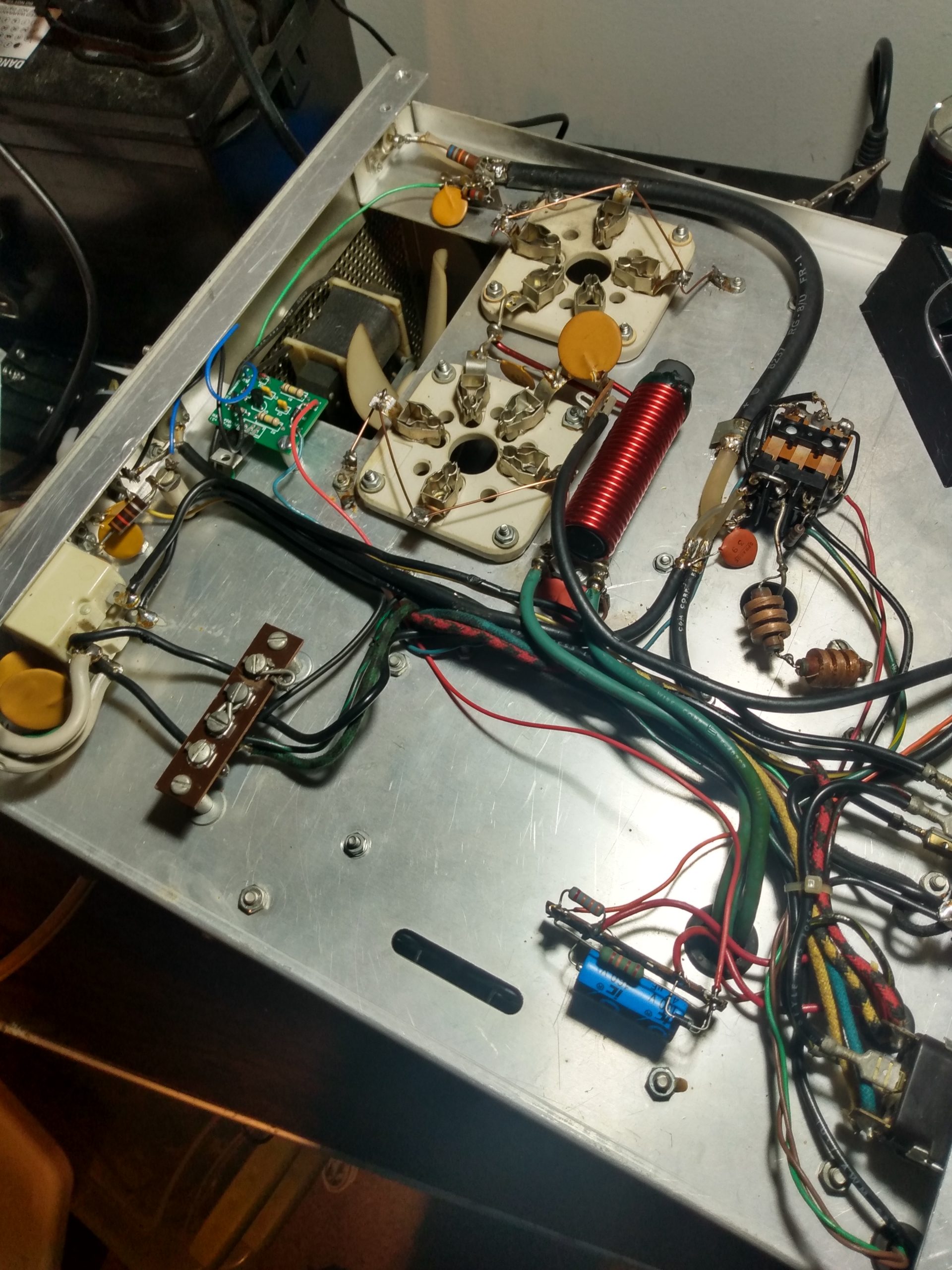
My next step was to flip the amplifier over and begin removing the stock grid circuitry on the tube sockets. I have heard Heathkit in its early days described as “bean counters designing amplifiers,” which might explain some design decisions. But why remove all these components just to ground the grids? I’ll let W8JI explain, because I can’t:
“The grid not only shields the input from direct RF feedback from the anode, it is also a good shield to prevent or minimize the anode voltage that might appear on the cathode during tube arcs. Floating the grid above ground is bad for RF, and bad for arc protection.”
Stock grid circuitryGrid circuitry removedUntrimmed capacitor leadsReady for groundingGrids grounded
Whoever built this SB-220 back in the 1970s did a good job. In fact, they did such a good job that I used almost an entire spool of solder wick getting the grid circuitry removed from the terminals and ground lugs. Not a single component lead had been clipped after soldering. Instead, the lead was wrapped around the terminal, up to 3 times, and completely covered with solder. The desoldering and removal process took well over an hour, and the grounding process took about 10 minutes. I used the same 18 gauge solid copper wire for grounding that I used to build the new parasitic suppressors for the tubes.
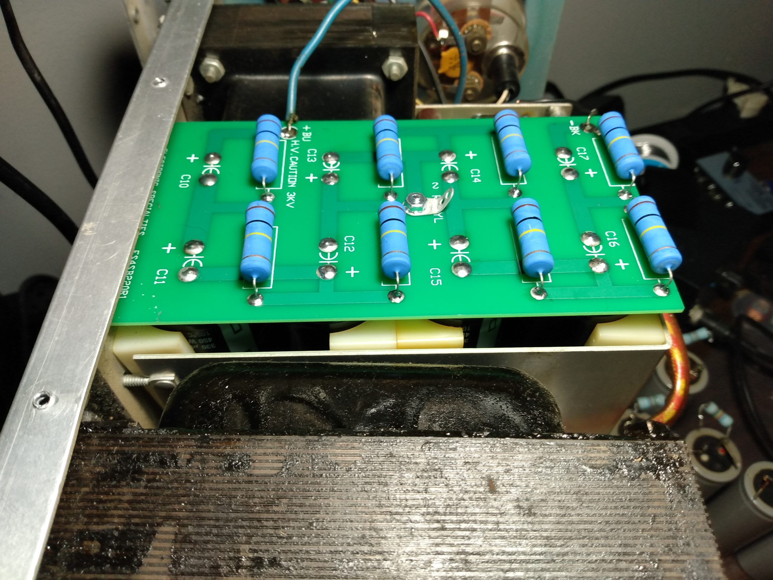
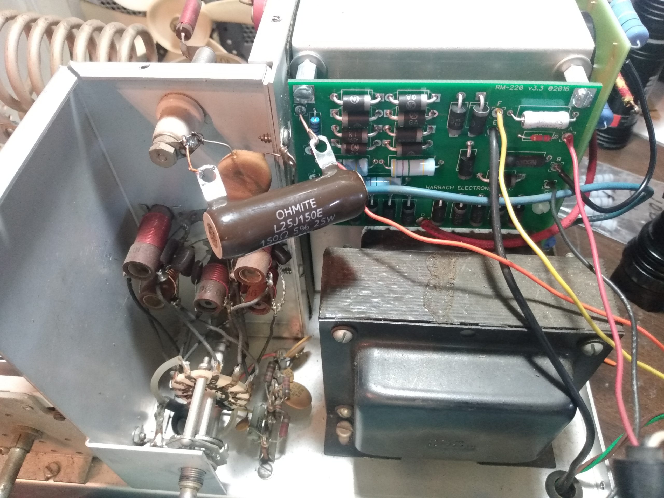
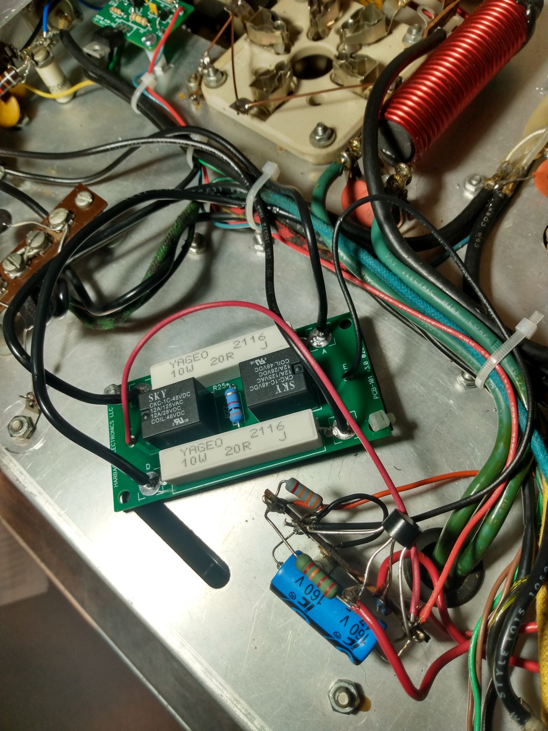
It was time to start putting the amplifier back together. I had built the new Harbach boards as soon as they arrived so they would be ready whenever I needed them. First to go in was the filter board. This board utilized the original plastic capacitor spacers. At first I tried to install the board using only 4 of the spacers, but I was not satisfied with this because the capacitors seemed to stress their connections to the board under their own weight (the board mounts vertically). I decided it was best to use all of the spacers, which took more time to shoehorn into the enclosure, but all the capacitors are securely in place and will not stress their solder joints. I left some space between the bottom of the capacitors and the board itself during its assembly to allow for better airflow and cooling.
Harbach RM-220 rectifier and meter boardHarbach ES4SB220 filter boardInstalled with 4 spacersGap for airflowPower board installationGlitch resistor (wired incorrectly)
Installation of the power board is pretty straightforward and simple because all wire leads to and from the high voltage transformer and the meters were all their original colors, so it was a matter of stepping down a checklist to connect these leads to the new board. I also installed a 150 ohm 25w “glitch resistor” on the HV connection to the tubes, which is an additional protection in case of filament to grid shorts. You might notice that this is wired improperly in the photo. I also noticed this, thankfully. The error was quickly resolved and the board was wired correctly before faceplate reinstallation.
Once again, it was time to flip the amplifier over, this time to install the soft key and soft start boards. There were several things that had to happen in a specific order for this to be successful. First, I had to get the boards mounted in place. Second, I had to replace the original AC circuit breakers with modern replacements. Third, all of these pieces had to be correctly wired to each other. Little did I know that I was signing myself up for an entire day of work for this part of the job.
First was the mounting of the soft key board. This was the easiest step, a mounting lug was provided and there was an unused chassis mounting bolt under the fan dedicated to this. So I mounted the soft key board and soldered the leads to their corresponding terminals, not knowing I’d be undoing this as part of the soft start board installation. Always read the full documentation before soldering.
Soft key board mountedSoft key board wired
Next was removal of the original AC circuit breakers. This was as frustrating as the removal of the grid circuitry, for the exact same reasons. Lots of solder was used in the original construction, and two capacitor leads were securely wrapped around the solder lugs. All of this, in a more confined space than the tube grid circuitry. Lots of big words were uttered.
Stock AC circuit breakersStock AC circuit breakersBreakers removed
It was at this point that I ran into a new challenge. While the Harbach soft key board came with a lug to mount the board to the amplifier chassis, the Harbach soft start board did not, and I didn’t have anything similar to mount it. So I would have to find another solution.
There is an “unused” bolt and nut between the AC terminal strip and the strip that connects to the 120v transformer, which is used to hold the capacitor bank in place. This is a suitable location for the soft start board, but it’s the only mounting point. Could I mount the board at only one point, and still prevent the board from moving around or shorting on the chassis?
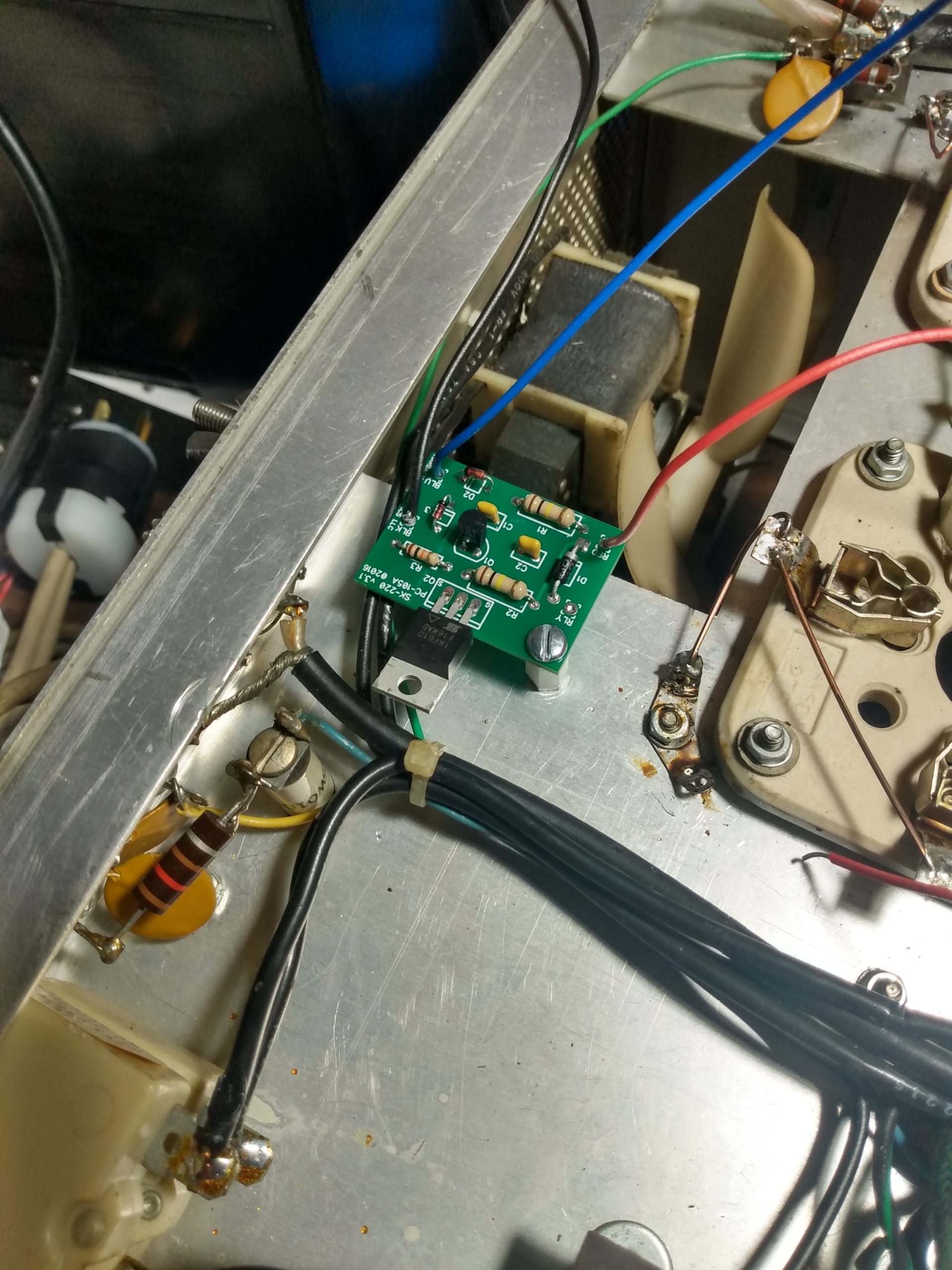
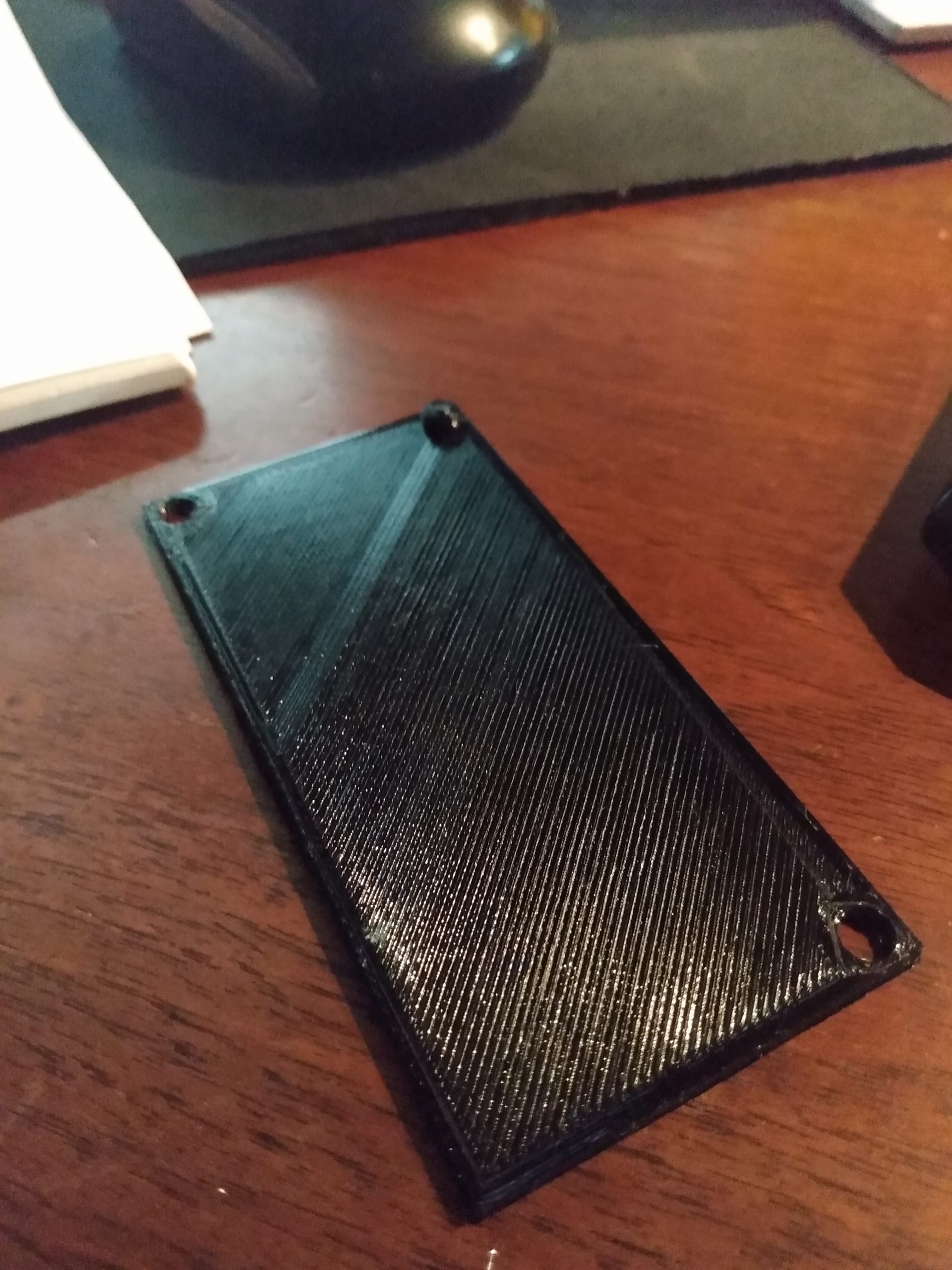
I measured the dimensions of the board and location of its mounting holes, designed a 1mm thick platform in Tinkercad, and 3d printed it using PETG. The platform has a notch on one of the corners that fits into an existing slot on the SB-220 chassis. One hole in the platform is for the mounting screw/bolt, another hole for a zip tie to hold the board in place over its platform, and the notch fits into the slot in the chassis, using the tension of the wires to the AC breakers keep the soft start board in place. It’s securely mounted and the remaining connections are ready to be wired up. Two diodes were wired in series on the transmit relay at this point as well.
PETG mounting board with notchSoft start board installedBoards wiredBoards and breakers installed and wired
Finally the day has arrived, it’s time to put the tubes back in their sockets and complete the SB-220 restoration. At this point it was almost three months to the day since I brought it home. Taking care to not get fingerprints all over the tubes or damage them in any way, they were inserted into their sockets, new lugs screwed to the anode caps, and the newly built parasitic suppressors were soldered into place.
I am not confident enough in my abilities to not kill myself with high voltage, so I decided it was best to put the amplifier back into its enclosure before powering it on. This also meant that in the event that something was wrong, I’d have to disassemble it again to get back into it. Being frustrated is better than being dead, so I spent about an hour putting the top cover back on and doing the required yoga to get the chassis back into its enclosure. It wouldn’t be so difficult if it wasn’t for the fact that the chassis weighs about 50lbs and has to float at precisely the correct position within the enclosure for the 4 plastic feet to screw perfectly into their threaded holes. I do not look forward to doing this again.
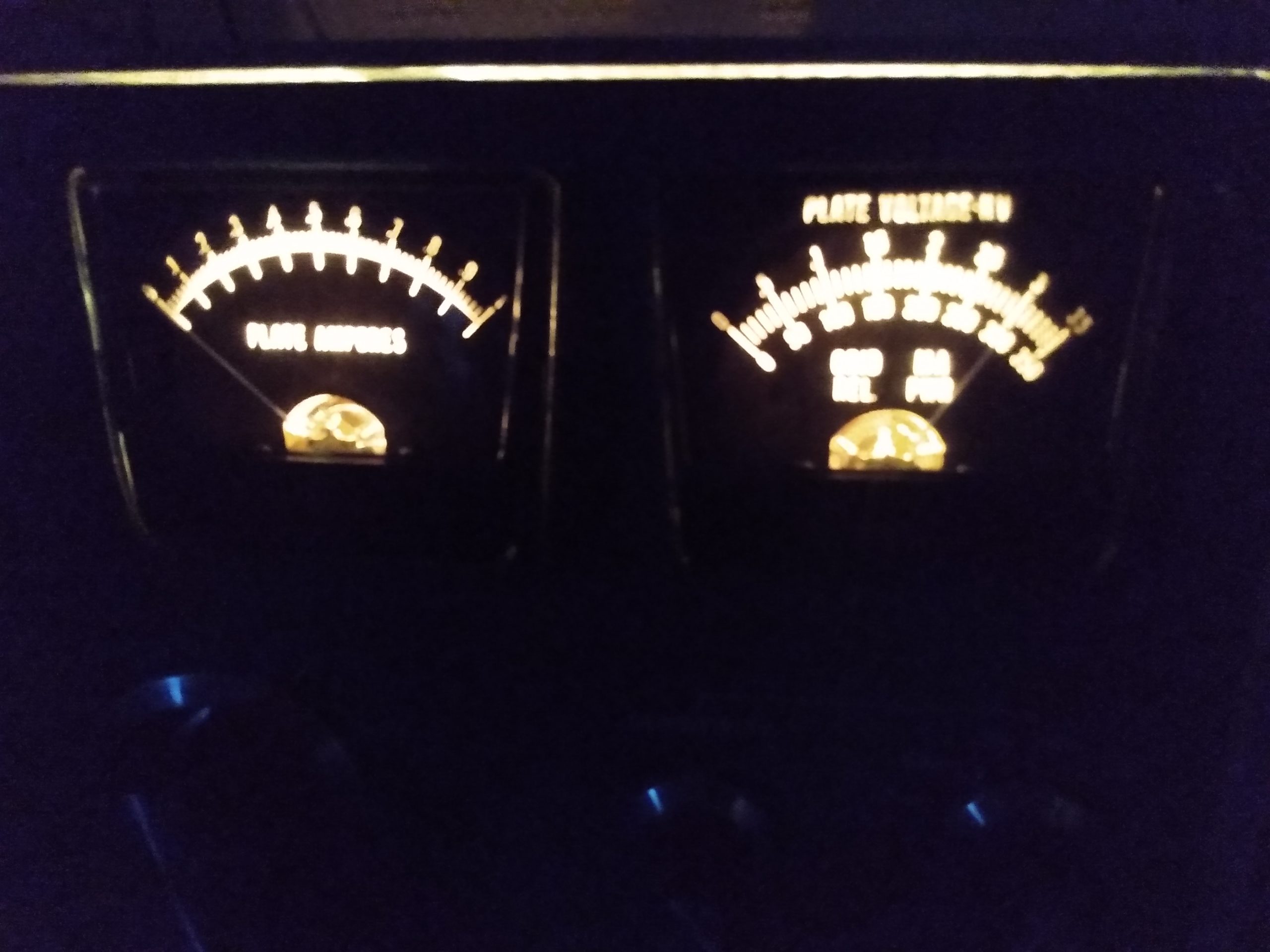
I ran a 240v extension cord from the outlet at my operating position over to the workbench. Then I spent 15 minutes pondering before hitting the switch. Would it turn on? Would it stay on? How much smoke would it give up? How loud would the tube explosion be? How do I explain it to the fire department? I finally grew a pair and hit the switch, and much to my surprise, the fan spun up, the meters lit, and the HV meter shot up to 3100v. Success!
Tubes and suppressors installed3100vComforting glow of 2x 3-500ZG
More Modifications
This is the end, right? Not quite. I noticed after screwing the feet into the bottom of the enclosure that the screws protruded below the feet and scratched the surface of my workbench. Also, these feet were a little high and I was concerned about the amp fitting into my radio rack with enough room for my tuner above it. So I decided to fire up the 3d printer again and give the SB-220 some new shoes. I printed 2cm high feet out of PETG that allowed the screw heads to recess into them. I also sourced 4 new screws from the hardware store that were 1/2″ shorter (cost: $0.04 USD), so the shorter feet would not cause the screws to protrude into the electrical components of the amplifier and cause an unexpected short. The amp sits like a lowrider, with just enough space below for adequate ventilation.
Original feetNew foot next to originalNew shoes
One modification that I wanted to do with this SB-220 was a standby switch. I operate a completely manually tuned shack, so there are times when I want to put 5w into an antenna to find a good tune, and that means having the amplifier out of the antenna system. Despite the 3-500ZG tube being “instant-on” and capable of being switched on and off repeatedly, I wanted to avoid the unnecessary stresses on the other components that come with these repeated power surges.
My original plan was to utilize the CW/SSB switch for an old-school standby switch and fan speed mod. A little history, condensed: This switch is a throwback to the days when the FCC required 1KW max input power on radio amplifiers for some reason (this was before my time so I’m murky on the details). These days this sort of thing isn’t required, and we are perfectly fine using the 2KW input that the SSB position on this switch provides. However, since I upgraded the keying circuit with the Harbach soft key mod, I wasn’t comfortable with the amount of modification I would have to do in order to get low voltage keying and the 120VDC of the fan circuit to coexist. I also could have added a toggle switch to the faceplate of the amplifier, but I wasn’t comfortable drilling new holes in what is a nice original faceplate.
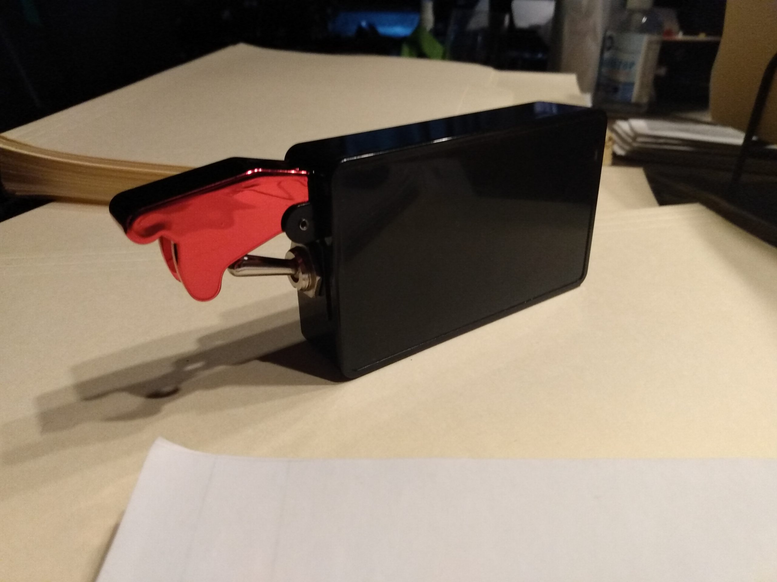
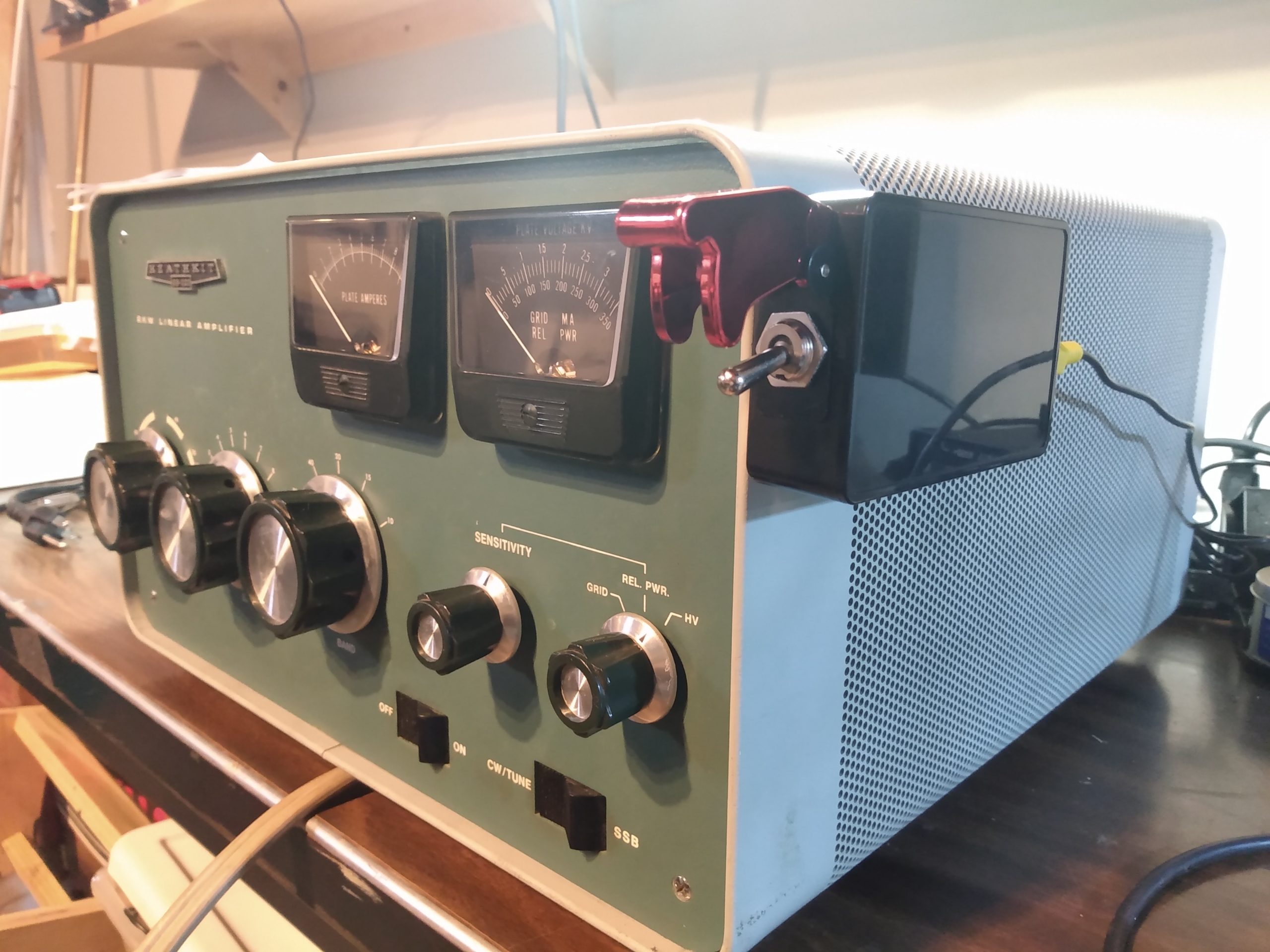
Instead, I would turn my keying cable into a standby switch. I wouldn’t get any fan speed modifications, but I would get standby operation. My original plan was to scavenge the required RCA connectors from an obsolete piece of consumer electronics, but the salvaged parts weren’t chassis mount connectors so I ended up scrapping that idea. Friend and neighbor Craig KC3MGN was nice enough to donate a pair of RCA chassis mount connectors to my project. I mounted these to a project box with a racing toggle switch, bonded the negative connections together, and ran the center conductor through the switch. With this box wired to the amplifier and the switch in the OFF position, keying up my radio would not key up the amplifier, leaving it in an on-but-standby state. With the red cover lifted and the switch in the ON (or GO BABY GO) position, the amplifier would key up as normal. I mounted the box to the side of the SB-220 with a strip of velcro, so there is no permanent defacement of the amp or enclosure.
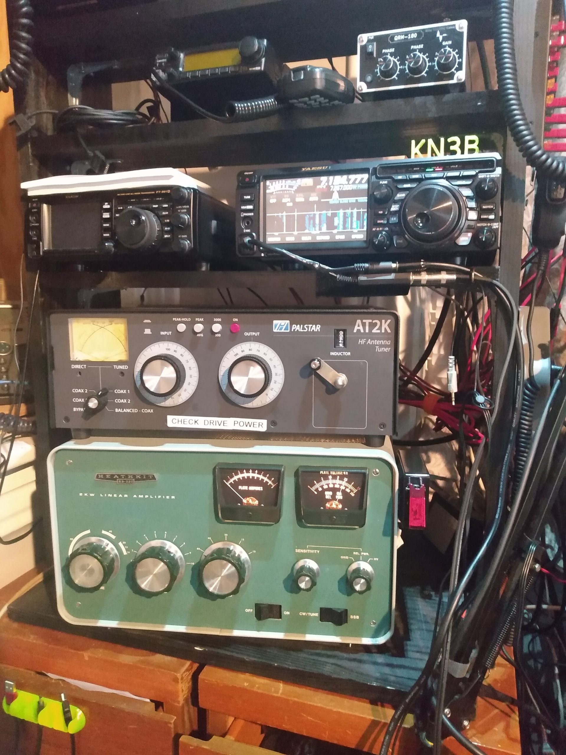
Donor electronicsGO BABY GO switchMounted to SB-220At home in the rack
The Heathkit SB-220 is still being tested, but it does put out a solid 1300+ watts on 40 and 80 meters, where it will be used the most. I have to do some antenna maintenance before I am comfortable attempting full power tests on the other bands, but early tests inspire confidence on 20, 15, and 10 meters.
Lessons Learned
This project took almost exactly 3 months to the day from picking up the amplifier to getting it on the air. After the cost of the amplifier, the Harbach kits, and several orders from Mouser, I believe I am in to the project for just under $1,000. I would do it all over again, if I were to find another SB-220 in the same or comparable condition.
Things I learned during this project:
Tube gear is resilient and can clearly take a lot of abuse. Even with the clear evidence of mistreatment and damage to some passive components, the rest of the amplifier was no worse for the wear.
Point-to-point wiring is so simple that you can work on it if you know how to flow solder. Don’t be intimidated by tube amplifiers, they are pretty simple and the schematics are easily digested if you know the basics.
Carefully inspect each and every circuit in your amplifier before you order parts from Mouser, otherwise you’ll spend about $35 in extra shipping charges because you had to order two capacitors five separate times over the course of the restoration.
And finally, if you find an old beat up tube amplifier for a good price, take it home and restore it before somebody else does.
I recently bought an old Icom IC-706 MKIIG for portable operation, so I wouldn’t have to pull my Yaesu FT450-D out of the shack when I wanted to radio from Delaware. It worked, but I didn’t realize how much I’d miss having an internal tuner, among other things.
So I sent it down the road and bought a gently used FT-991A, which I have used before and scratches the all-band, all-mode itch.
My goal was to build a portable setup that fits into a single Apache case, which I quickly realized was not possible with the 706. The 991A provides a single cable interface for audio, CAT, and PTT, which really simplifies portable digital operation. So I found a deal on a refurbished Lenovo ThinkPad tablet, which conveniently also fits in the case with the radio.
There is already a lot of info available regarding the digital settings for the 991A, and despite this being my second 991A setup adventure, I still had a few issues getting a signal from WSJT-X to the antenna. This seems very common. It is a lot of learning curve in a small package, and has the menu options to prove it (153 options, to be exact).
Configuration of the FT-991A for digital operation with WSJT-X can be broken into three parts: software, radio, and audio settings.
Software Configuration
Before connection the radio via USB, the Yaesu virtual com port drivers should be installed. Once the radio is connected, there will be two COM ports added, one that is used for CAT and one for RTS. Keying can also be done over PTT or VOX.
Radio tab:
Serial Port: COM3
Baud Rate: 4800
Data Bit/Stop Bit/Handshake: Default
PTT Method: RTS
PTT Port: COM4
Mode: USB
Split Operation: None
Audio tab:
A big part of the appeal of the FT-991A is the built-in audio interface. With the drivers installed and radio connected via USB cable, there are two sound devices (microphone and speaker) marked USB AUDIO CODEC. Input is microphone, output is speaker. You’ll know you have the wrong audio device selected when you attempt to transmit via WSJT-X and the screams of the damned erupt from your PC speakers.
Radio Configuration
I performed a factory reset on the FT-991A when it arrived, so these are the menu options that were changed from their defaults.
031 CAT RATE: 4800bps – This can be any value as long as WSJT-X and radio configs match.
032 CAT TOT: 100msec
062 DATA MODE: OTHERS
066 DATA LCUT FREQ: OFF
068 DATA HCUT FREQ: OFF
070 DATA IN SELECT: REAR
071 DATA PTT SELECT: RTS
072 DATA PORT SELECT: USB
106 SSB MIC SELECT: REAR
108 SSB PTT SELECT: RTS
109 SSB PORT SELECT: USB
The SSB options are necessary because the software is using USB rather than USB-DATA. Otherwise the software will be able to PTT, but no audio will be transmitted. This is one of the more common issues I came across when researching the “radio keys up but no power out” problem.
Audio Configuration
At this point, WSJT-X should be able to change the frequency via CAT control and key up the radio. If done properly, there may even be something transmitted. A lot of operators will stop here and scream into the bands without adjusting input/output levels, as is tradition. If you notice your ALC meter go into the red during TX, you are one of these operators.
In the [F/M-LIST] menu, DT gain should be rolled back to about 10, and adjusted up from there. Otherwise distortion may occur.
The audio levels on the PC side are adjusted via the sound settings in the operating system. Input level via Microphone (USB AUDIO CODEC) should be adjusted to a level that maxes the receive meter in WSJT-X at around 60db.
Receive will probably still work if the audio level isn’t set properly, but transmit requires a little more finesse. It is very easy to send distorted audio by sending it too loud. On my Thinkpad, adjusting Speakers (USB AUDIO CODEC) to an output level of 10 is barely audible to the radio. An output level of 50 pushes the ALC into the red. A setting of 25 seems ideal.
Now that I have everything configured, I can throw this radio into an Apache case and forget about it until I go to Delaware for the weekend.