Month: January 2023

2023 ARRL January VHF Contest

Living on the floor of a valley in the Appalachian Mountains doesn’t make for very good day-to-day weak signal VHF operating.  Normally I don’t bother doing 2 meter operation unless it’s talking to one of the nearby mountaintop repeaters.  But the January and June VHF contests are the exception, and I take these opportunities to set up portable operation on a nearby ridge.

The contest didn’t start until 2PM local time, so I eased into my morning by drinking some coffee, working on some QBM, and working some 10 meter sideband DX before the North American QSO Party started. 

I arrived at my operating location, the intersection of PA Route 554 and Skyline Drive, at precisely 1PM.  I chose this location not because it is the best ridge to operate VHF from (I’m sure it’s not), but because it is only about 4 miles as the crow flies from my home station, is in the same grid square (FN11), and is about 1500 feet in elevation compared to 500 feet of elevation at my QTH on the valley floor. 

Conditions were approximately 32 degrees and overcast, typical January weather in Pennsylvania.  The area I operated from serves as a parking area for people utilizing the nearby hiking trails, so there were several cars taking up space.  Luckily the owners of these cars emerged from the woods just as I was trying to figure out where to park, so I secured an ideal spot. 

In the June 2022 VHF contest I had beams for 2 meters and 6 meters.  My 6 meter beam isn’t really meant to be repeatedly broken down and transported, so I decided to stick to 2 meters for this trip.  I was doing this portable operation alone and it would simplify setup and tear down. 

Unwashed vehicle with mast and beam

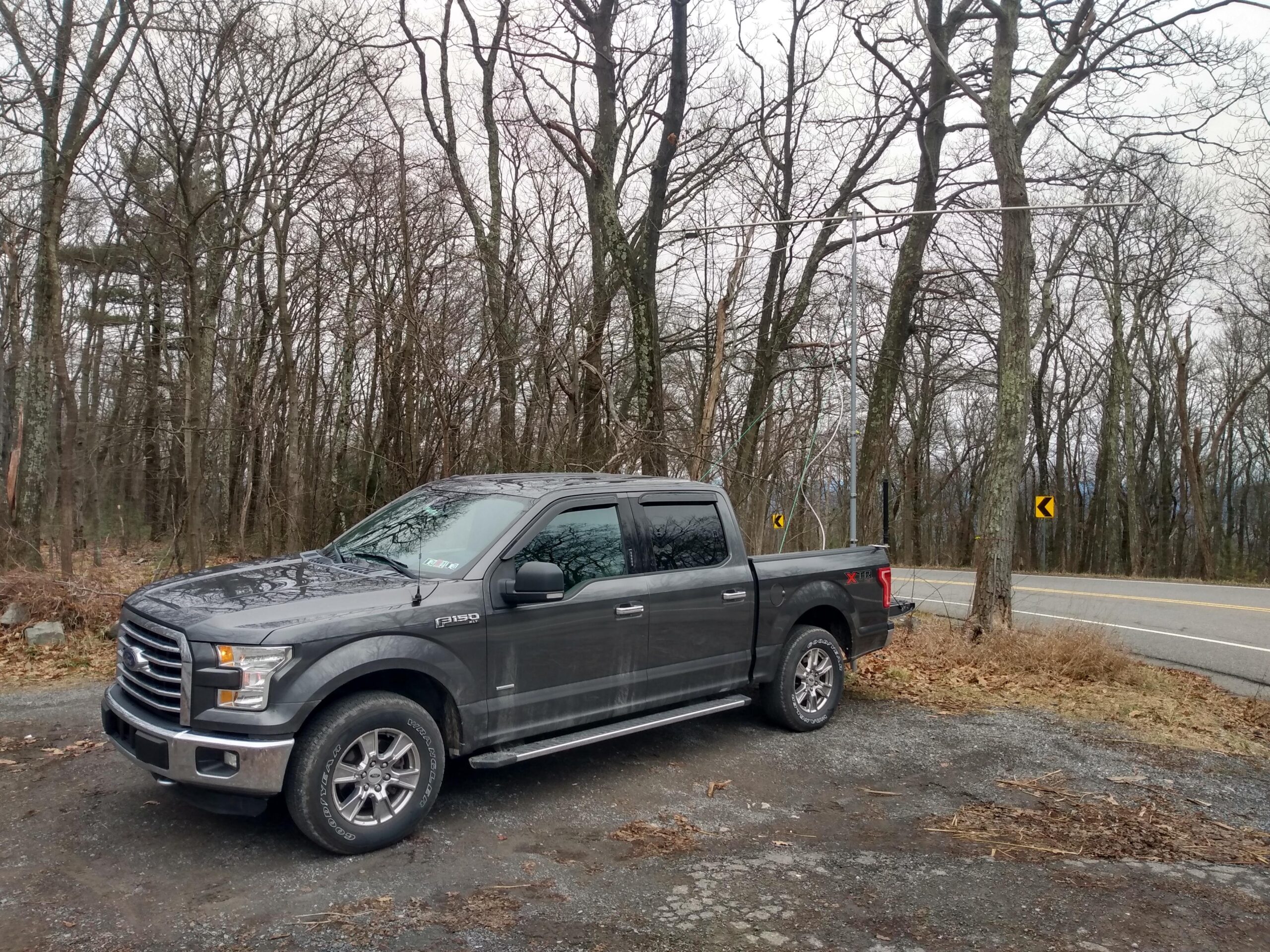
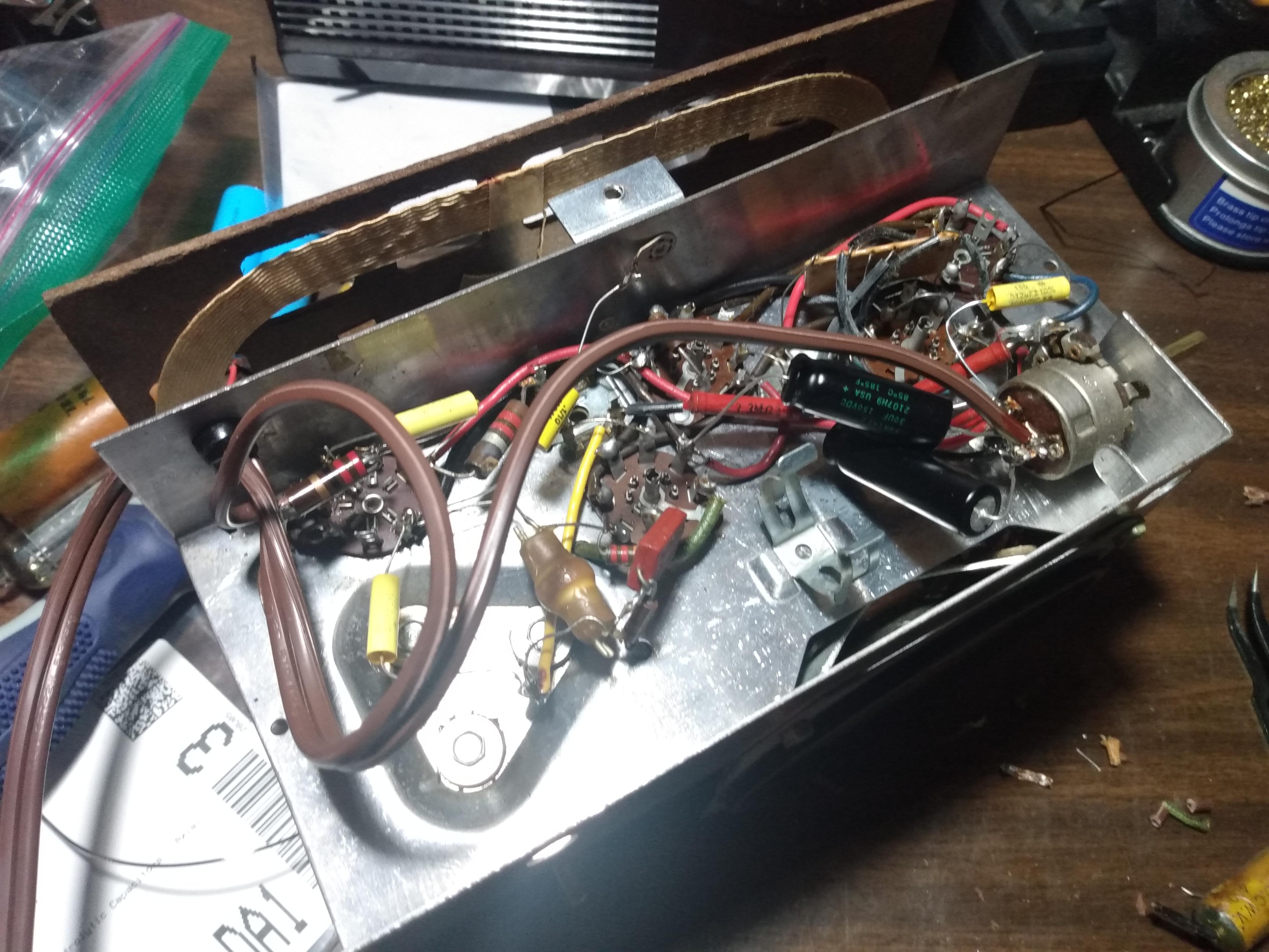
The antenna I use for 2 meters is an older Cushcraft 13B2 yagi that was generously given to me by Dale N3ZIO.  When I received it, it was missing a couple elements, but MFJ was able to get them to me (eventually) for a few dollars each.  It has 13 elements and provides 15.8 dBi of gain, a 26dB front-to-back ratio, and is about 15 feet long.  It breaks down into 3 pieces for transport, which is just about perfect for fitting into the bed of my truck.

Cushcraft 13el 2m beam

The mast the beam is mounted to is nothing more than a Harbor Freight telescoping flag pole with hose clamps to lock the sections in place.  It’s not an elegant piece of hardware, but it was affordable and easily holds the weight of the beam.  I should also mention that this particular mast’s bottom two sections are kind of stuck together, so actual height is only about 17 feet.  This is fine for 2 meter work, since it puts the beam more than 2 full wavelengths above the ground.  The plastic hooks on the mast (where a flag would normally attach) are excellent mounting points for guy lines, because they allow the mast to rotate, which means the beam can rotate as well.

The mast is held upright by a trailer hitch mast mount.  The mount is long enough for the tailgate to be lowered with the mast in place, which makes mounting the beam to the mast very easy.  I mounted the center section of the beam with the mast in its lowered position, attached the front and rear using a single stove bolt for each, connected the LMR400 coax to the antenna, and began raising the beam. 

As I raised the beam, I also guyed it using paracord to two cleats at the front of the truck bed, and a tree directly behind the truck.  I used some high visibility 3D printed paracord hooks to keep the lines tight.  Surprisingly, there was no wind at this operating position so I would not have to stress test the limits of the paracord hooks.  Perhaps another time.

Operating position
Operating position

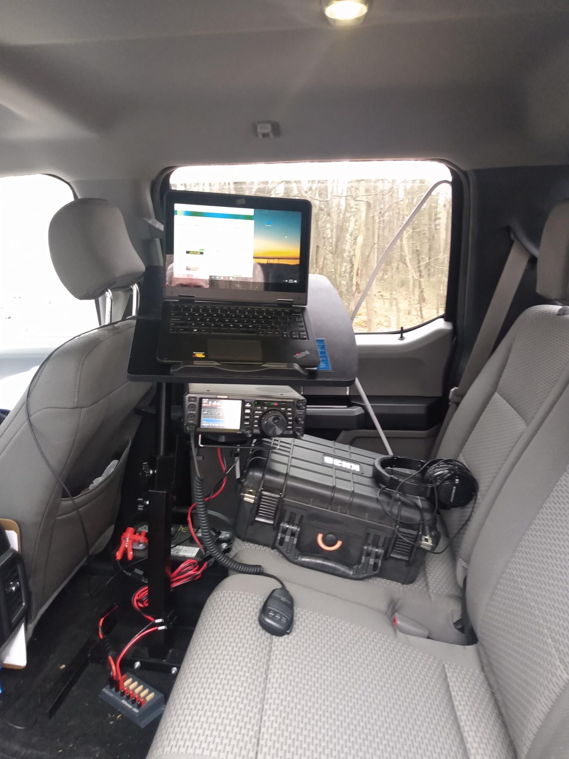
During the June VHF contest, I’ll set up a tent and a table and some chairs.  January is a pretty unpleasant time to be outdoors in PA, so this time I decided to set up the operating position in the backseat of my truck.  There is more than enough room for a small table, deep cycle marine battery, FT991a, and my laptop.  I could run the heat in the truck and only have to get out to spin the beam. 

The contest started promptly at 2PM.  I was tuned to FT8 and immediately heard stations calling CQ.  Dave KC3JNW was my first QSO on the very first contest-legal FT8 cycle.  The first few minutes were a frenzy of the stations that could hear each other working each other, and it quickly slowed down. 

I switched to SSB phone and worked a few stations, and then back to FT8 again.  This cycle repeated a few times as the other stations moved between modes.  I would hear a station on FT8, look them up on QRZ, point the beam in their general direction, and try to work them.  I picked up a few stations this way. 

A highlight of SSB phone was working Chris K2CR in two separate grid squares.  As we had our second QSO, the clock struck 5PM and I decided it was time to pack up. My longest SSB QSO was either N2NT or K2CR at around 147 miles, and my longest FT8 QSO was to VA3IKE at 295 miles.  Total was 27 FT8 QSOs (including a couple dupes) and 7 SSB QSOs, all on 2 meters.  I am satisfied with these numbers.

Most FT8 QSOs were made with 25 watts, all SSB QSOs were made with 50w (maximum power on 2 meters with the FT991a).  My deep cycle battery is a year old and does dip below 12v under load, but it had more than enough capacity to run the radio for 3 hours.  I should start planning for its replacement.

I returned home at about 6PM and failed to make any QSOs on 6 meters.  So I ended my evening casually S&Ping some NAQP SSB traffic on 20 and 40 meters.   

One improvement I would like to make is adding an antenna switch and an omnidirectional 2 meter antenna.  Working with only a beam can be difficult, and I don’t know how many stations I wasn’t hearing due to possible nulls in the pattern.  I will ponder the antenna situation and come up with new experiments for June VHF.

Posted by kn3b in Amateur Radio, 0 comments

Antique Radio Restoration – RCA Victor Model 3-X-521

I own a few antique AM broadcast radio receivers through unfortunate side effects of being a ham, but I’ve never repaired one.  I’ve seen them in Pennsylvania antique malls, but never tried a repair or restoration myself because I didn’t think I was capable.  After becoming a fan and subscriber of Mr Carlson’s Lab on Youtube, I had warmed up to the idea of buying one and giving it a shot.

If you’ve never been to a central PA antique mall, they are lousy with junk that people think is worth its weight in gold.  Cast iron cookware is especially overpriced due to this phenomenon (and its weight), and I’ve bought and sold enough cast iron pans to stop treating them as an investment.  But antique AM radios are ever-present, and a lot of them are very affordable.  Seems like nobody is able or willing to take the time and effort to restore them.  Probably because nobody wants to buy them after they are fixed.  AM radio is basically dead anyway, right?

Quite a while ago I was in one of these antique malls with my wife and I found this RCA Victor from 1953 for $25.  It was in very good shape on the outside, all the knobs moved as they should with no problems, and the original “instruction” sheet (I think the most accurate comparison would be the “tag” on a mattress today) was still on the bottom of the radio.  I didn’t have the tools at the time, or the permission from the seller for that matter, to remove the back and peer inside.  But for $25, it would make a good conversation piece.  I bought it without further question.

It was an RCA Victor Model 3-X-521.  The power cord was dry and cracking under the slightest bit of stress, meaning it couldn’t be plugged in until that was replaced.  There was some flaking of the tuning knob paint, but that wouldn’t affect anything.  But the good news: Everything mechanical worked without any physical resistance and there was no obvious damage that indicated water or neglect.  With any luck, it would be a great candidate for a simple restoration.  I got it home, put in on the bench, and cracked it open.  It was 100% original and no rust was present.  So of course, I put it on a shelf on top of another old radio and said to myself, “I will fix this someday.”

Life tends to get in the way of a lot of my hobbies and projects.  It’s taken a while, but I’ve learned to accept this.  I usually get to the projects I really want to complete.  About a year passed, and only after acquiring a few tools (variac, mostly) and some experience (lots of soldering), I was ready to tackle a very simple restoration of a radio with very few components.

The interior condition of the radio is on par with the exterior. Some dust, but otherwise original and undamaged. The tuning capacitor was very clean and straight. Flipping the radio over, you can see that it was completely original. Clearly visible are four wax paper capacitors, and a “multi-section cardboard” capacitor that contained two polarized capacitors of different values. All of these capacitors need to be replaced no matter how they test. They are well past due at about 70 years old.

I wasn’t able to plug the radio into my new Chineseium variac because of the disintegrating power cable, so I didn’t know if the radio worked at all, and I didn’t want to add a power cable before I had all the usual suspects (capacitors) replaced anyway. The condition of the radio, originality of the parts, and lack of any obvious catastrophic failure gave me optimism that the radio would work after I did the bare minimum.

I began by removing the power cord by cutting it on either side of the chassis and removing the grommet. I left short leads in place so I knew where the new power cord needed to go. This took a while, it didn’t want to give up the grommet. The leftover lead on one side of the power cord would not stay in place for long, because it got in the way of removing the first .5MF capacitor.

There was an immediate lesson learned at this point in the old capacitor removal process. This radio doesn’t have a PCB, because they didn’t exist in 1953. Everything is point-to-point wiring, and most points are on a pin connected to a tube socket. Using solder wick to remove the old solder heated up the sockets to the point where the pin would start to wiggle, meaning something was melting just enough to allow for that movement. The lesson here: Just clip the leads of the old components, making note where everything was connected, and then clean up the terminals on the tube socket when everything is out of the way. This minimizes the heating time on the tube socket and decreases the likelihood of melting something that shouldn’t be melting. The old capacitors are useless anyway, no need to preserve their lead length.

So the first .5MF capacitor and one side of the AC power line were removed. A resistor shared the same terminal as the AC line on one side, and the .5MF capacitor on the other side. I completely removed it so I could get a better look at the socket, making sure to note where everything was connected.

The replacement capacitors were a lot smaller than the original wax paper capacitors, which made dealing with the point-to-point wiring a little bit easier. The first three capacitors were closely located, so after replacing the first I ended up replacing the next two at the same time. This process didn’t take as long as the first because I just clipped the leads and cleaned the terminals up without the capacitor in the way.

I turned my attention to the wax paper capacitor on the other side of the radio, and the multi-section cardboard cap that shared the on/off/volume switch. This was a crowded part of the radio, so I took several pictures from different angles. First I removed the .015MF wax capacitor, and replaced the unobstructed lead with one end of the replacement capacitor. This capacitor shared its other lead with other components on the on/off/volume switch, it would be soldered in place once all other connections were ready. I then removed the multi-section cardboard capacitor, making sure to leave enough of the color coded leads in places so I knew where they went.

The multi-section cardboard capacitor is actually two polarized electrolytic capacitors in one housing with separate positive leads and a shared negative. This was apparently a common thing back in the 1950s, and the solution to this is to just replace it with two modern electrolytic capacitors with the same values as the originals. It’s a good thing that the modern electrolytic replacements came with long leads, because they were necessary to get them both to fit without shorting to the chassis.

Wiring the electrolytic capacitors wasn’t eventful, they went in as expected with just enough room to bend them into compliance without shorting to the chassis. The last step was to add a new power cord. I salvaged a polarized plug and twinlead power cable from an old unused extension cord that matched the original brown. I reused the strain relief grommet that held the original power cable. The positive connection on the new power cord went to the appropriate terminal on the on/off/volume switch, and neutral to the terminal on the tube socket pin that the resistor was attached to in the first step of this restoration.

All done! I rushed to slide the chassis back into the body of the radio, applied knobs to their respective potentiometer shafts, inserted the one retaining screw, and plugged the radio into the variac. After about 15 seconds (tube warmup time) and at around 110v AC, I heard things: https://imgur.com/PDXPEBa

I don’t consider this a full restoration, but I do consider this stage of this project to be complete. There is still a buzz across the entire AM band that I want to address, and I’d like to clean up the paint on the tuning knob. Some takeaways:

  • There are plenty of schematics available online for antique radios, but I wasn’t able to find one for this specific model, at least not one that was in a resolution that I could read. I’ll keep searching before I do any more work on this, because I think it will be necessary to resolve the buzzing.
  • Paper capacitors removed all tested within ~20% of spec, but the large electrolytic was >30% so it definitely needed replacement. Great after 70 years, but they needed to be replaced. I’ll keep them in a box for science experiments.
  • I learned a little about old AM radios and I’m ready to apply this to the next project (already acquired).

This certainly wasn’t a comprehensive restoration, but an old radio works again and that’s enough for now. If anybody has a readable schematic for an RCA Victor Model 3-X-521, please let me know.

Posted by kn3b in Electronics, 0 comments